Passive Components Blog
No Result
View All Result
  • Home
  • NewsFilter
    • All
    • Aerospace & Defence
    • Antenna
    • Applications
    • Automotive
    • Capacitors
    • Circuit Protection Devices
    • electro-mechanical news
    • Filters
    • Fuses
    • Inductors
    • Industrial
    • Integrated Passives
    • inter-connect news
    • Market & Supply Chain
    • Market Insights
    • Medical
    • Modelling and Simulation
    • New Materials & Supply
    • New Technologies
    • Non-linear Passives
    • Oscillators
    • Passive Sensors News
    • Resistors
    • RF & Microwave
    • Telecommunication
    • Weekly Digest

    3-Phase EMI Filter Design, Simulation, Calculation and Test

    YAGEO Unveils Compact 2.4 GHz SMD Antenna

    KYOCERA AVX Releases Antenna for Iridium Satellite IoT Applications

    Molex Releases Industry-First Quad-Row Board-to-Board Connectors with EMI Shields

    Image credit: Samtec

    How to Match the Right Connector with Protocol Requirements

    Smoltek CNF-MIM Capacitors Pass 1,000h Reliability Test

    Capacitor Lead Times: October 2025

    Paumanok Unveils Aluminum Capacitor Foils World Markets Study 2025-2030

    Coilcraft Introduces Ultra-Low Loss Shielded Power Inductors

    Trending Tags

    • Ripple Current
    • RF
    • Leakage Current
    • Tantalum vs Ceramic
    • Snubber
    • Low ESR
    • Feedthrough
    • Derating
    • Dielectric Constant
    • New Products
    • Market Reports
  • VideoFilter
    • All
    • Antenna videos
    • Capacitor videos
    • Circuit Protection Video
    • Filter videos
    • Fuse videos
    • Inductor videos
    • Inter-Connect Video
    • Non-linear passives videos
    • Oscillator videos
    • Passive sensors videos
    • Resistor videos

    3-Phase EMI Filter Design, Simulation, Calculation and Test

    Transformer Design Optimization for Power Electronics Applications

    Common Mode Chokes Selection for RF Circuits in Next-Generation Communication Systems

    Capacitor Self-balancing in a Flying-Capacitor Buck Converter

    How to Select Ferrite Bead for Filtering in Buck Boost Converter

    Power Inductors Future: Minimal Losses and Compact Designs

    Percolation Phenomenon: Degradation of Molded Power Inductors in DC/DC Converters

    Connector PCB Design Challenges

    Efficient Power Converters: Duty Cycle vs Conduction Losses

    Trending Tags

    • Capacitors explained
    • Inductors explained
    • Resistors explained
    • Filters explained
    • Application Video Guidelines
    • EMC
    • New Products
    • Ripple Current
    • Simulation
    • Tantalum vs Ceramic
  • Knowledge Blog
  • Suppliers
    • Who is Who
  • PCNS
    • PCNS 2025
    • PCNS 2023
    • PCNS 2021
    • PCNS 2019
    • PCNS 2017
  • Events
No Result
View All Result
Passive Components Blog
No Result
View All Result

Low Inductance, Direct Power DC Bus for Electric Drive Systems

17.4.2020
Reading Time: 4 mins read
A A

Recently, a team at Sandia National Laboratories developed and patented an interesting approach to DC power bus for electrical vehucles with low resistance, low inductance but also sufficient capacitance to smooth out voltage ripple.

As DC currents increase along with switching frequencies in applications such as electric vehicles and hybrid electric vehicles, the performance demands on the DC power bus go beyond just the IR drop (i.e. voltage drop) and thermal considerations. That bus must now have very low inductance at higher frequencies into the hundreds of kilohertz, driven by design demands and the increased use of wide bandgap devices (WBG) represented by silicon carbide (SiC) and gallium nitride (GaN) switches.

RelatedPosts

3-Phase EMI Filter Design, Simulation, Calculation and Test

YAGEO Unveils Compact 2.4 GHz SMD Antenna

KYOCERA AVX Releases Antenna for Iridium Satellite IoT Applications

The bus must have low resistance and low inductance but also sufficient capacitance to smooth out voltage ripple. Unfortunately, the same capacitors used for that second attribute are detrimental to the first one due to their interconnect and internal parasitics. Different approaches can be used to try to the multiple conflicting goals, in addition to simply adding more bulk capacitance.

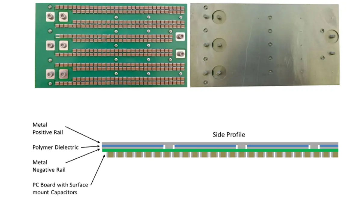
Sandia National Laboratories design uses a layered, PC board-like construction with two metal planes separated by a polymer dielectric to provide “planar” capacitance, Figure 1.

Fig. 1. The power bus looks like a PC board but with a polymer dielectric rather than glass-epoxy, so it functions as a planar capacitor. (Source: Sandia National Laboratories)

This base capacitance is boosted by a large number (in the hundreds) of small multilayered ceramic capacitors (MLCCs) — rather than the customary electrolytic or film capacitors — connected between the planes using standard PC board vias, Figure 2.

Fig. 2. The top and bottom views of the assembled board show the large number of MLCC devices as well as the large, uninterrupted “ground” plane. (Source: Sandia National Laboratories)

This approach provides both electrical and thermal benefits. The spread-out placement of so many capacitors reduces shunt impedance to high-frequency current components, and the flat ceramic capacitors can tolerate higher temperatures and support better airflow. There are other benefits as well. In existing applications, the positive and negative (often called ground) rails use bus bars, and these are separated by a large area; as the magnetic field lines cross this larger area, there is a higher effective inductance due to the large current loop. The Sandia Laboratories plate-based approach greatly reduces the inductance by decreasing the area of the current loop.

Their prototype board used 2-ounce cladded PC-board material and measured about 6 × 11 × 0.062 inches thick (150 × 280 × 1.6 mm). It was populated with 336 0.15 µF/1000 V MLCC devices (with X7R dielectric and AEC – Q200 qualified, for automotive use). Total capacitive was 50.4 µF, which their models and simulations indicated would be sufficient to keep ripple below a target value at 100 kHz.

In addition to extensive modeling, they tested this design from 100 Hz to 10 MHz with an impedance-measurement instrument, Figure 3, and those results closely matched their model. They also compared their results to an available model of a bus used in a similar way in a Toyota Prius. Their bus had somewhat superior performance, was physically smaller, and could withstand higher temperatures.

Fig. 3. The test result of impedance versus frequency showed the performance of the simulated and physical units tracked closely and was better than the existing bus in a Toyota Prius. (Source: Sandia National Laboratories)

Summary

The low-inductance DC power bus demonstrates substantial reductions in parasitic inductance over conventional DC link systems by using a printed circuit board and carefully controlled capacitor placement to maximize planar capacitance. Utilizing ceramic rather than standard electrolytic or film capacitors helps to achieve higher operating temperatures and improved thermal management. Parallel capacitor placement provides low shunt impedance to high-frequency current components and smooths current spikes created by switching operations. Beyond electric vehicle drive systems, this system may be relevant in electric drive applications where high-frequency switching and/or high temperature operations are desired.

Benefits

  • Reduced parasitic inductance
  • High frequency operation (>100 kHz) 
  • High temperature operation and improved thermal management 
  • Increased power density with reduced overall size 
  • Supports WBG devices 
  • May be fabricated with simple PCB assembly methods

Applications and Industries

  • Automotive 
  • Electric drive systems / electric vehicles 
  • High frequency switching 
  • Grid-tied power systems 
  • Geothermal 
  • Oil and gas

Related

Source: Sandia National Laboratories

Recent Posts

3-Phase EMI Filter Design, Simulation, Calculation and Test

6.11.2025
11

Molex Releases Industry-First Quad-Row Board-to-Board Connectors with EMI Shields

6.11.2025
2

Smoltek CNF-MIM Capacitors Pass 1,000h Reliability Test

6.11.2025
5

Capacitor Lead Times: October 2025

6.11.2025
19

Paumanok Unveils Aluminum Capacitor Foils World Markets Study 2025-2030

6.11.2025
6

Coilcraft Introduces Ultra-Low Loss Shielded Power Inductors

6.11.2025
5

Würth Elektronik Expands its MagI³C-VDMM MicroModules

5.11.2025
8

Exxelia Presents Smart Integrated Magnetics Solution at Space Tech Expo 2025 

5.11.2025
14

Littelfuse Releases Load-Powered Compact Relay

5.11.2025
10

Murata Expands High Cutoff Frequency Chip Common Mode Chokes

5.11.2025
7

Upcoming Events

Nov 11
17:00 - 18:00 CET

Industrial Applications Demand More from Interconnects in Next-Gen Designs

Nov 12
11:00 - 12:00 CET

PCB Design: Impedance is for everyone!

Nov 12
November 12 @ 12:00 - November 13 @ 14:15 EST

Microelectronic Packaging Failure Modes and Analysis

View Calendar

Popular Posts

  • Buck Converter Design and Calculation

    0 shares
    Share 0 Tweet 0
  • Boost Converter Design and Calculation

    0 shares
    Share 0 Tweet 0
  • LLC Resonant Converter Design and Calculation

    0 shares
    Share 0 Tweet 0
  • Flyback Converter Design and Calculation

    0 shares
    Share 0 Tweet 0
  • Ripple Current and its Effects on the Performance of Capacitors

    3 shares
    Share 3 Tweet 0
  • MLCC and Ceramic Capacitors

    0 shares
    Share 0 Tweet 0
  • Dual Active Bridge (DAB) Topology

    0 shares
    Share 0 Tweet 0
  • What is a Dielectric Constant and DF of Plastic Materials?

    4 shares
    Share 4 Tweet 0
  • SEPIC Converter Design and Calculation

    0 shares
    Share 0 Tweet 0
  • Flying Capacitors

    0 shares
    Share 0 Tweet 0

Newsletter Subscription


Passive Components Blog

© EPCI - Leading Passive Components Educational and Information Site

  • Home
  • Privacy Policy
  • EPCI Membership & Advertisement
  • About

No Result
View All Result
  • Home
  • Knowledge Blog
  • PCNS

© EPCI - Leading Passive Components Educational and Information Site

This website uses cookies. By continuing to use this website you are giving consent to cookies being used. Visit our Privacy and Cookie Policy.
Go to mobile version