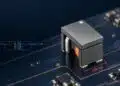
Molded power inductors are widely used in compact DC/DC converters because their powder-composite magnetic material can support low-profile construction, high current capability, and soft saturation behaviour. Würth Elektronik describes a degradation mechanism termed the percolation phenomenon, in which electrical and thermal stress can compromise insulation between magnetic particles and increase magnetic-core loss over time.
For engineers, the key point is that conventional inductance and DC-resistance checks may not always reveal this degradation early. A converter can retain an apparently normal nominal inductance while its high-frequency loss behaviour, thermal margin, ripple-current waveform, and EMI performance change.
Key Takeaways
- The Percolation Phenomenon affects molded power inductors, resulting in insulation degradation and increased magnetic-core loss.
- Conventional measurements may not detect this degradation, even if nominal inductance appears normal.
- Engineers must differentiate percolation from other effects like DC-bias saturation and copper loss for accurate diagnostics.
- Elevated voltage and temperature are stress factors that can accelerate percolation-related degradation in inductors.
- A robust qualification approach should account for realistic operating conditions, stress factors, and material behavior.
What is the percolation phenomenon?
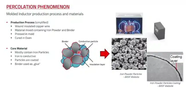
Molded power inductors are commonly produced by compacting coated soft-magnetic powder around a copper conductor and stabilising the structure with a binder system. The coating and binder regions help electrically isolate neighbouring magnetic particles, which reduces inter-particle circulating currents and associated AC losses.
Würth Elektronik uses the term percolation phenomenon for a material-degradation process in which this inter-particle electrical insulation progressively degrades. As more electrically conductive paths form between particles, the magnetic composite can transition from predominantly insulated behaviour towards a more conductive network. This creates an additional loss mechanism within the magnetic body.
The supplier’s presentation associates the effect with prolonged exposure to elevated electrical stress, elevated temperature, or their combination. The severity, onset, and practical consequence depend on the specific magnetic powder, coating system, binder, component construction, applied voltage waveform, temperature, operating time, and converter duty cycle.
Why molded inductors are affected
A molded inductor differs from a conventional ferrite-core construction because its magnetic path is formed from many electrically insulated powder particles. The distributed air-gap characteristic of the material can help provide a gradual inductance reduction with DC bias rather than abrupt hard saturation.
The particle insulation is therefore important for more than mechanical processing: it limits electrical interaction between adjacent conductive magnetic particles. If this isolation weakens locally, additional current paths can form inside the magnetic composite and raise high-frequency loss.
The supplier describes the mechanism as involving both particle coating and binder behaviour. Increasing coating thickness alone is not necessarily a complete solution, because it can also alter magnetic permeability, distributed-gap behaviour, available inductance values, saturation characteristics, and package performance.
Percolation versus other effects
A rising converter temperature or changing ripple current does not automatically indicate percolation. Engineers should differentiate the reported effect from normal DC-bias saturation, copper loss, conventional frequency-dependent core loss, and mechanical damage.
| Effect | Primary driver | Typical electrical signature | Useful diagnostic approach |
|---|---|---|---|
| DC-bias saturation | Excessive peak inductor current | Effective inductance falls as current rises; ripple current increases immediately with load | Measure inductance versus DC bias and compare with the datasheet curve |
| Copper loss | RMS current and winding resistance | Predictable temperature rise linked to winding loss | Check DCR, AC resistance, current, and winding temperature |
| Conventional core loss | Switching frequency, flux swing, and temperature | Loss increases according to the material and operating point | Compare operation with supplier loss data and thermal models |
| Percolation-related degradation | Electrical and/or thermal stress accumulated over time | High-frequency Q and impedance change; increased loss; ripple-waveform distortion | Compare frequency sweeps and converter waveforms before and after stress exposure |
| Mechanical cracking or termination damage | PCB strain, vibration, or thermal cycling | Intermittent operation, open circuit, DCR shift, or abrupt inductance change | Inspect mechanically and perform continuity, DCR, and inductance tests |
The reported phenomenon is distinct from normal saturation because the supplier’s examples show a progressive, stress-history-dependent change in loss behaviour rather than only an immediate current-dependent reduction of inductance.
Electrical model and circuit impact
A simplified representation of the reported degradation adds a loss-related resistance in parallel with the ideal inductor. This is a useful conceptual model rather than a complete compact model, because the effect is nonlinear and depends on frequency, temperature, applied stress, and degradation state.
For an ideal buck-converter inductor during the switching interval in which the input is applied:
In normal operation, a stable inductor and stable converter conditions produce a predictable ripple-current slope. When additional loss develops in the magnetic body, the current waveform and input-power demand can change even where a basic inductance measurement remains close to its initial value.
Würth Elektronik’s presentation illustrates that the effect can appear as a change from a clean triangular ripple-current waveform towards a distorted waveform with additional harmonic content. In a real converter, this may reduce efficiency, increase inductor temperature, change conducted or radiated EMI margins, and affect system-level power consumption.
Stress factors and feedback
The presentation identifies elevated voltage and elevated temperature as stress factors that can initiate or accelerate the reported degradation. Fast-switching converters deserve particular attention because a nominal bus voltage does not fully describe the voltage stress at the inductor; ringing, overshoot, layout parasitics, and switching transients can all influence the applied waveform.
Temperature affects both short-term loss and long-term material ageing. Higher magnetic loss raises component temperature, while higher temperature may accelerate degradation of coating or binder systems. Under unfavourable conditions, this can form a feedback process:
Würth Elektronik describes a potentially accelerating progression after conductive networks become established. The practical outcome remains application-specific, so engineers should not infer a common threshold temperature, voltage, or operating-life limit from the illustrative test cases alone.
Key features and benefits
- Compact molded construction: Powder-composite magnetic material enables low-profile, space-efficient power inductors for densely populated DC/DC converter boards.
- Soft saturation characteristic: Molded inductors can provide a more gradual inductance reduction under increasing DC bias than hard-saturating magnetic structures, which can support controlled converter behaviour during overload conditions.
- Reliability-focused material selection: The webinar highlights that coating, binder, powder composition, compaction process, and conductor technology can all affect long-term material behaviour.
- High-frequency diagnostic value: Frequency-dependent Q-factor and impedance measurements can reveal changes that may be missed by a conventional single-frequency inductance and DCR measurement.
- Application-specific qualification: A realistic mission profile can identify risks that generic component checks may not capture, particularly where high temperature, long operating time, voltage overshoot, or continuous duty are involved.
Detecting percolation-related degradation
The supplier reports that conventional measurements around 100 kHz may not clearly reveal the effect in all cases. The winding remains intact and nominal inductance or series resistance can therefore appear normal, while higher-frequency Q-factor and impedance characteristics have changed.
A practical engineering evaluation should combine component-level measurement with converter-level observations.
- Establish a baseline for input power, output power, efficiency, inductor temperature, ripple-current amplitude, and EMI performance at a defined operating point.
- Measure inductance, Q factor, impedance magnitude, and phase across a frequency range that includes the converter switching-frequency region and the higher-frequency range relevant to the component.
- Where test equipment permits, measure under appropriate DC bias and temperature conditions rather than relying only on small-signal, room-temperature LCR data.
- Compare the pre-stress and post-stress ripple-current waveform, including peak-to-peak ripple, waveform shape, switching transients, and harmonic spectrum.
- Examine both operating and storage stress conditions, since the webinar identifies elevated voltage and elevated temperature as possible routes to degradation.
- Do not clear an inductor as a root cause solely because nominal inductance and DCR remain within expected limits.
Design-in notes for engineers
- Define the actual voltage stress. Evaluate the inductor voltage waveform at the PCB, including switching-node ringing and transient overshoot, rather than using only nominal input and output voltages.
- Use the complete thermal mission profile. Include ambient temperature, self-heating, airflow, enclosure conditions, expected operating duration, on/off cycling, and peak-load duty cycle.
- Select with DC bias and losses in mind. Rated current, saturation current, and nominal inductance are necessary selection parameters, but they do not replace loss, temperature-rise, and lifetime validation. See the guide to current-dependent inductors in buck converters and PFC stages for related current-dependent behaviour.
- Control switch-node transients. Optimised layout, gate-drive tuning, snubbers, clamp networks, or other transient-control methods can reduce unnecessary voltage stress in high-speed converter designs.
- Validate at end of life, not only at start of life. Perform design verification with representative electrical and thermal stress, then confirm efficiency, thermal margin, control-loop behaviour, output ripple, and EMC performance after ageing.
- Request relevant supplier data. For critical applications, ask for test conditions, duration, applied waveform, temperature, sample population, measurement method, acceptance criteria, and the specific component family covered by the data.
- Treat high-reliability systems separately. Automotive, industrial always-on equipment, telecom infrastructure, renewable-energy converters, and data-centre power applications may warrant extended qualification against a defined lifetime mission profile.
Application fit
| Application | Why molded inductors are used | Reliability considerations |
|---|---|---|
| Point-of-load buck converters | High current in a compact PCB area | Check DC bias, ripple-current heating, switching-node overshoot, and continuous-duty temperature |
| Automotive DC/DC converters | Compactness, mechanical robustness, and high-current capability | Use the intended automotive-qualified series and validate the vehicle thermal and electrical transient environment |
| Industrial control and automation | Long service life and potentially high ambient temperature | Consider 24/7 operating time, enclosure airflow, overload events, and long-term thermal margin |
| Telecom and networking power rails | High power density and continuous operation | Validate efficiency drift, inductor heating, transient response, and conducted-EMI margin |
| Renewable-energy and battery systems | Variable load, high power, and elevated ambient temperature | Assess thermal cycling, peak operating conditions, and switching transients throughout the mission profile |
| AI and server power delivery | High-current multiphase conversion and dense board layouts | Check local temperature rise, multiphase current sharing, high-frequency switching behaviour, and long-term power efficiency |
Qualification approach
A robust qualification plan begins with the converter rather than the inductor alone. Define the electrical, thermal, environmental, and lifetime conditions that the installed component will experience.
- Characterise the initial design: Record electrical waveforms, efficiency, temperature, ripple current, and EMI margin at nominal, peak, and representative transient conditions.
- Identify realistic stresses: Include operating voltage, overshoot, switching frequency, DC bias, ripple-current amplitude, ambient temperature, self-heating, operating duration, and duty cycle.
- Run representative ageing: Use a test duration and temperature profile appropriate for the product lifetime and risk level. Manufacturer test results should be interpreted only within their stated conditions.
- Repeat component and system measurements: Compare frequency-domain component characteristics with converter-level efficiency, ripple waveform, thermal image, and EMC results.
- Document design margin: Retain the measured thermal, electrical, and EMI margins for design release, supplier comparison, and future change control.
For buck converters, verify the inductor using the complete circuit conditions described in the Buck Converter Design and Calculation guide rather than treating inductance as an isolated nominal value.
What the Würth Elektronik webinar shows
The Würth Elektronik webinar presents its findings from research into elevated-voltage and thermal ageing of molded power inductors. It explains the powder-and-binder construction, differentiates the observed effect from ordinary saturation, and uses Q-factor and impedance-versus-frequency measurements to show changes not always visible through traditional inductance and series-resistance tests.
The presentation also discusses tests extended beyond 1,000 hours to 5,000 hours and illustrates an Arrhenius-style extrapolation method for a defined degradation criterion. Such extrapolations are specific to the tested parts, stress conditions, assumptions, and failure definition; they should not be generalised as an all-inductor lifetime rule.
The webinar further states that thicker insulation alone is not necessarily the answer because it can compromise other magnetic and mechanical properties. The appropriate solution is a balanced material and construction design combined with realistic application validation.
Conclusion
Percolation-related degradation is a useful reliability concept for engineers working with molded power inductors in demanding DC/DC converter applications. The main practical lesson is that nominal inductance and DCR alone may not be sufficient to assess long-term behaviour, especially where elevated temperature, electrical stress, switching transients, and continuous-duty operation are present.
For design teams, the most effective response is application-specific validation: define the true voltage and thermal mission profile, measure the inductor in-circuit as well as on the bench, and confirm end-of-life efficiency, ripple-current behaviour, and thermal margin rather than relying only on beginning-of-life datasheet checks.
FAQ
No. Saturation is primarily a current-driven reduction of effective inductance, while the reported percolation phenomenon is described as a progressive material-degradation effect linked to electrical and thermal stress over time.
Yes. According to the webinar discussion, nominal inductance and DCR can remain close to expected values while higher-frequency Q and impedance behaviour, converter losses, or ripple-current waveform have already changed.
No. The practical risk depends on the powder material, insulation system, binder, mechanical construction, voltage waveform, temperature, operating time, and supplier-specific design approach.
Useful checks include ripple-current waveform, efficiency drift, inductor temperature rise, EMI margin, and frequency-dependent impedance or Q-factor changes before and after stress testing.
No. Molded inductors remain highly useful for compact, high-current power designs. The key requirement is realistic qualification against the actual application stress profile.
How to evaluate percolation risk in a design
Use the following workflow when a molded power inductor is considered for a thermally or electrically demanding converter design:
- Define the mission profile, including input voltage range, load profile, switching frequency, ripple current, ambient temperature, airflow, duty cycle, and expected lifetime.
- Measure the actual inductor voltage waveform on the PCB, including ringing and overshoot, rather than relying only on nominal converter voltages.
- Characterise the selected inductor at relevant frequency, DC bias, and temperature conditions, including Q factor and impedance behaviour where possible.
- Run the converter at realistic thermal stress and monitor efficiency, ripple-current waveform, inductor temperature, and EMI behaviour over time.
- Re-check the component after stress exposure, comparing pre- and post-test impedance, Q, waveform shape, and thermal behaviour.
- Confirm that the converter still meets electrical, thermal, and EMC targets with adequate margin at the intended end-of-life condition.
Further reading
- What Is an Inductor?
- Inductors Core Materials and Their Losses
- Current-Dependent Inductors: Using Non-Linear Inductance in Buck Converters and PFC Stages
- Buck Converter Design and Calculation
Source
This article is based primarily on the Würth Elektronik technical webinar on the impact of elevated voltage and temperature on molded power inductors in DC/DC converters. Engineers should consult the current manufacturer datasheet, application notes, qualification information, and product-specific documentation before final component selection and design release.
References
- Würth Elektronik webinar: Impact of Elevated Voltage and Temperature on Molded Power Inductors in DC/DC Converters
- Würth Elektronik eiSos