


The rapid rise in vehicle electrification presents new challenges to source cutting-edge components that can handle higher temperatures and voltages without sacrificing reliability, availability, and footprint. Brandon S. Peeler, Key Account Manager – Automotive for Knowles Precision Devices explains benefits of multilayer ceramic capacitors in such applications.
As governments around the world tighten emissions standards, the global demand for electric vehicles (EVs) is rapidly increasing. For EV design engineers and manufacturers, increased electrification results in the challenge of finding cutting-edge components that can handle the unique demands of EVs. Generally, this includes functioning at higher temperatures, voltages, and power without sacrificing reliability, availability, or footprint.
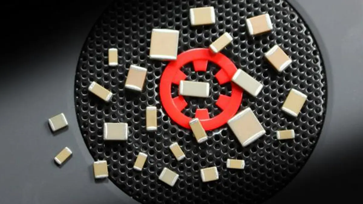
To that end, multilayer ceramic capacitors (MLCCs) have emerged as a perfect component for EV electronics and subsystems, since these tiny capacitors have high temperature and offer an easy surface-mount form factor (Fig. 1).
Capacitor Requirements for EVs
Recently, MLCCs have become one of the key building blocks for control electronics. However, for an MLCC to qualify for use in an EV, the component must meet these tougher demands:
- High voltage: EV systems are based on high-voltage battery systems, so capacitors must be rated for increased voltage ranges such as 250 to 400 V for plug-in hybrid electric vehicles (PHEVs), 800 V for commercial vehicles, and 48 V for hybrid electric vehicles (HEVs).
- High power: To compete with petroleum-based vehicles that can refill in minutes, EV manufacturers need ultra-fast charging solutions, including EV systems that can handle increasing amounts of power and charge directly from the grid.
- Smaller size: A vehicle’s size and weight affects its overall energy efficiency. Thus, EV subsystems must have smaller footprints, which increases component density inside the system. This means components need to provide the same high performance in reduced package sizes.
- High temperature: The combination of increased voltages, higher converter frequencies, and smaller footprint together creates a high-temperature environment that can be detrimental to standard parts.
- Industrial reliability: Automotive-grade capacitors need to meet stringent standards and withstand the most demanding environments that require superior mechanical performance under incredibly harsh operating conditions.
MLCCs: A Great Fit for These Five Common EV Subsystems
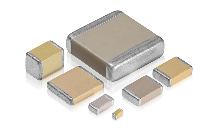
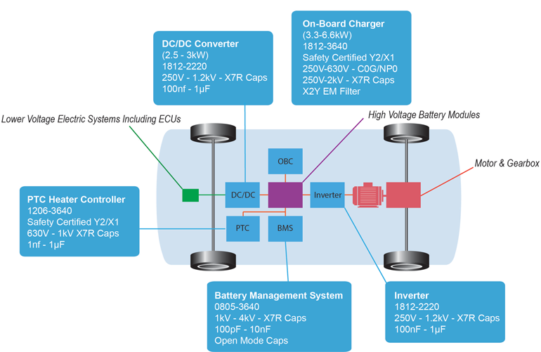
Modern EVs, HEVs, and PHEVs are sparking a revolution in capacitor technology targeting subsystem electronics. Due to the higher temperatures inside the control circuits, conventional plastic film capacitors are no longer suitable for all applications, and ceramic MLCCs are now increasingly used in EV subsystems (Fig. 2). Let’s examine the requirements and challenges presented by each of these subsystems as well as the types of MLCCs commonly used in each one.
1. Battery Management System (BMS)
The goal of the BMS is to monitor and control the cells within a high-voltage battery stack, which includes the following functions:
- Monitoring the battery cells’ voltage, current, temperature, and overall condition
- Providing diagnostic data for the battery
- Managing the current among cells (also known as cell balancing)
- Protecting the battery from over or under charging
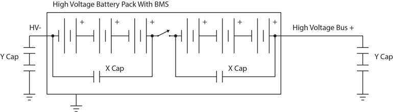
To help suppress the effects of electromagnetic and radio frequency interference (EMI/RFI), Safety Certified capacitors are commonly used at the input and output of major functional blocks, like the BMS. Class Y safety capacitors at the high-voltage bus and Class X safety capacitors for each cell module are added for protection from EMI noise disturbance (Fig. 3).
Class X and Class Y capacitors are most commonly available as ceramic or plastic film RFI/EMI suppression capacitors. However, given the high temperature and tiny size requirements for the BMS, MLCCs are the only viable option that will not melt in BMS operating conditions.
2. On-Board Charger (OBC)
The purpose of the OBC is to charge the traction battery, usually in a range of 48 to 800 V. Functions of the OBC include:
- Converting alternating current (ac) from the electric grid into direct current (dc) that charges the vehicle’s battery.
- Providing power factor correction (PFC) to shape the input current to a power supply, maximizing efficiency and reducing harmonics.
- Adjusting the produced dc voltage up or down to provide the correct dc levels to the battery.
To accomplish these tasks, the primary sections of an OBC and the corresponding capacitors for each circuit may contain:
- An EMI or ac line filter: Safety Certified capacitors are used to absorb the noise on the ac line and must have high reliability and meet appropriate safety regulations (e.g., UL, CSA, VDE).
- A PFC circuit: The PFC input capacitor smooths the pulsating dc voltages produced from the ac rectifier and must have comparably high capacitance.
- A dc link between the ac-dc and dc-dc converters: The dc link capacitor must be able to handle twice the line frequency. Common circuit arrangements include ceramic capacitors connected in parallel with other capacitor technologies to achieve this goal.
- A dc-dc converter: One type of dc-dc topology is called the LLC converter. This uses a resonant capacitor to tune a series or parallel resonant circuits at operating frequencies in the hundreds of kilohertz. The output filter capacitor removes the ripple component of the ac current and smooths the output voltage of the power converter.
It’s also worth noting that many manufacturers now offer bidirectional OBCs that can convert residual power from the vehicle battery and feed it back to the grid. As a result, higher MLCC component counts are used in bidirectional OBCs.
3. DC-DC Converter
In EVs, the dc-dc converter subsystem is required to transfer energy between the high-voltage battery and low-voltage (e.g., 12 V) systems. The vehicle’s high-voltage systems supply large loads like the traction motor, air conditioner, and starter, while the lower-power system is used for components such as infotainment systems, sensors, and safety.
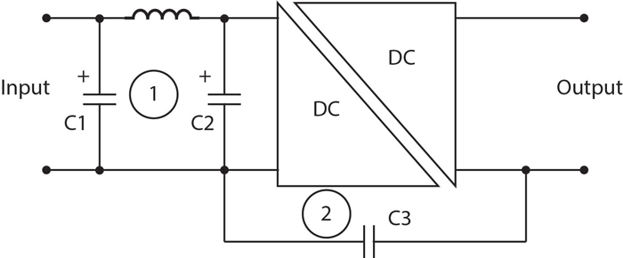
Two types of capacitors are commonly used in DC/DC converters (Fig. 4):
- C1 and C2: These EMI filters or input capacitors are utilized for noise countermeasures and require high capacitance.
- C3: The primary-secondary coupling capacitor connects the primary and secondary ground lines to reduce the common-mode noise in the secondary side caused by the primary-side switching noise. The high-voltage rating of the class Y capacitor must equal the insulation voltage of the transformer.
As with the BMS subsystem, ceramic capacitors instead of film capacitors are a better option for withstanding the high operating temperatures of the dc-dc converter.
4. Inverter
Inverters convert dc power from the battery to three-phase ac power to drive the traction motors. Important performance metrics for inverter systems include power-handling capabilities, efficiency, reliability, and thermal performance. Typical motor control functions include:
- Converting from dc to ac during acceleration and ac to dc during braking.
- Driving the insulated-gate bipolar transistor (IGBT) power stages.
- Detecting the speed and position of the motor.
- Diagnosing and managing potential issues to avoid inverter breakdown.
Two capacitors are commonly used in inverter subsystems:
- The dc link or smoothing capacitor: This capacitor is placed between the dc (battery) and ac (load) sides of the voltage inverter. Due to the high capacitance requirements, small-sized MLCCs can be used together with film and aluminum electrolytic capacitors to integrate closer to the IGBT switching device and improve high-frequency attenuation.
- The snubber capacitor protects the power switching module by absorbing noise caused by 100- to 300-kHz high-frequency operation.
5. Positive-Temperature-Coefficient (PTC) Heater Controller
Unlike petroleum-based cars that warm up the cabin using the combustion engine’s waste heat, EVs use high-voltage PTC heaters as the heat source for the HVAC system. PTC heaters provide a comfortable cabin environment for passengers while also maintaining optimal operating temperatures for the batteries. This allows the batteries to properly start and charge the car in cold weather.
PTC heaters use specialized materials that, when cold, have lower electrical resistance, enabling full current to flow and heat to be generated. As the temperature rises, the resistance of the PTC material also increases. This property acts as an automatic safety feature that limits the current flow and prevents overheating.
In this subsystem, the power-supply-unit (PSU) circuitry requires high-voltage capacitors for snubber and primary-secondary isolation purposes. Furthermore, Class X and Y filter capacitors are needed at the input of the high-voltage PTC circuit to provide EMI filter and noise countermeasures.
Complying with Industry Standards and Certifications
In addition to meeting the general specifications required for these EV subsystems, plus having the ability to function reliably in the harsh environments inside an EV, component manufacturers should also be IATF 16949-certified and compliant with AEC-Q200.
Published by the International Automotive Task Force (IATF), IATF 16949 is a technical specification for quality management that establishes company-wide policies, processes, and documentation requirements for the automotive supply chain. IATF 16949 ensures certified parts manufacturers meet an optimal level of quality when producing automotive-grade components for Tier 1 suppliers and OEMs.
Compliance with the AEC-Q200 Stress Test Qualification for Passive Components, as determined by the Automotive Electronics Council (AEC) Component Technical Committee, is also essential. By subjecting capacitors to rigorous thermal, mechanical, and other stress testing, this standard raises the bar for automotive versus standard capacitors. Poor mechanical design and material selection can result in component failure and short circuits. Thus, AEC-Q200-qualified MLCCs are specifically built with a focus on reliability and robustness to function even in the harshest automotive environments.
Choosing the Right MLCC Supplier
Not only is it critical for EV manufacturers to determine the right capacitor for each EV subsystem, it’s also highly important to select the right component supplier that truly understands the stringent requirements and harsh operating conditions of the EV space. Traditional automotive experts are accustomed to working with 12- or 24-V applications, whereas EV systems operate at medium to high voltages ranging from 250 V to as much as 800 V. The right supplier will not only offer the appropriate range of high-voltage, high-capacitance, and small-size capacitors, but a highly experienced supplier will also advise you early on in the research and design process to ensure you avoid costly mistakes.


