





Passive Components Blog
No Result
View All Result
  • Home
  • News
    • All
    • Aerospace & Defence
    • Antenna
    • Applications
    • Automotive
    • Capacitors
    • Circuit Protection Devices
    • electro-mechanical news
    • Filters
    • Fuses
    • Inductors
    • Industrial
    • Integrated Passives
    • inter-connect news
    • Market & Supply Chain
    • Market Insights
    • Medical
    • Modelling and Simulation
    • New Materials & Supply
    • New Technologies
    • Non-linear Passives
    • Optoelectronics and Isolation
    • Oscillators
    • Passive Sensors News
    • Resistors
    • RF & Microwave
    • Telecommunication
    • Weekly Digest
    Illustration of a thin-film capacitor stack with TiN electrodes and an ultrathin hafnium zirconium oxide ferroelectric layer on silicon

    Sub-Volt Ferroelectric HZO Capacitor Pairs Speed and Endurance

    Cut-open lithium-ion capacitor pouch cell showing stacked carbon electrodes and separators, with vials of carbon powder

    Lithium-Ion Capacitor Review Backs Hard Carbon//AC Pairing

    Rack power shelf in an AI data center with film DC-link capacitors, a supercapacitor bank and a converter board

    800 VDC AI Data Centers Reshape Capacitor Demand for 2027

    Schematic of a titanium nitride thin-film inductor within a CMOS poly-resistor stack beside its integrated resonator circuit.

    TiN Superinductors Bring Compact Cryogenic Inductance to CMOS

    Close-up of reddish-brown metallic rocks illustrating TTI MarketEYE’s connector raw material cost analysis

    Connector Raw Material Costs Rise 20.9% in Q2 2026

    AI and Passive Components: Structural Growth Beyond Data Centers

    YAGEO PMT6397 push-pull transformer with a segmented toroidal winding and surface-mount terminals

    YAGEO Releases Push-Pull Transformers for Isolated 3 W Supplies

    Transformer Losses and Thermal Design: Modelling and Validation

    DMASS Europe Q3 2026 electronic component distribution market overview

    European Component Distribution Jumps 42.7% in Q3 2026

    Trending Tags

    • Ripple Current
    • RF
    • Leakage Current
    • Tantalum vs Ceramic
    • Snubber
    • Low ESR
    • Feedthrough
    • Derating
    • Dielectric Constant
    • New Products
    • Market Reports
  • Knowledge Blog
  • Dossiers
    • Aerospace and Defense Passive Components Dossier
    • AI Hardware Dossier
    • Automotive Dossier
    • Industrial Robotics Dossier
    • Power Converter Dossier
    • Capacitor Dossier
    • Circuit Protection Dossier
    • Inductor Dossier
    • Resistor Dossier
    • Silicon Capacitors and Integrated Passives Dossier
  • Suppliers
    • Who is Who
  • PCNS
    • PCNS 2025
    • PCNS 2023
    • PCNS 2021
    • PCNS 2019
    • PCNS 2017
  • Events
  • Home
  • News
    • All
    • Aerospace & Defence
    • Antenna
    • Applications
    • Automotive
    • Capacitors
    • Circuit Protection Devices
    • electro-mechanical news
    • Filters
    • Fuses
    • Inductors
    • Industrial
    • Integrated Passives
    • inter-connect news
    • Market & Supply Chain
    • Market Insights
    • Medical
    • Modelling and Simulation
    • New Materials & Supply
    • New Technologies
    • Non-linear Passives
    • Optoelectronics and Isolation
    • Oscillators
    • Passive Sensors News
    • Resistors
    • RF & Microwave
    • Telecommunication
    • Weekly Digest
    Illustration of a thin-film capacitor stack with TiN electrodes and an ultrathin hafnium zirconium oxide ferroelectric layer on silicon

    Sub-Volt Ferroelectric HZO Capacitor Pairs Speed and Endurance

    Cut-open lithium-ion capacitor pouch cell showing stacked carbon electrodes and separators, with vials of carbon powder

    Lithium-Ion Capacitor Review Backs Hard Carbon//AC Pairing

    Rack power shelf in an AI data center with film DC-link capacitors, a supercapacitor bank and a converter board

    800 VDC AI Data Centers Reshape Capacitor Demand for 2027

    Schematic of a titanium nitride thin-film inductor within a CMOS poly-resistor stack beside its integrated resonator circuit.

    TiN Superinductors Bring Compact Cryogenic Inductance to CMOS

    Close-up of reddish-brown metallic rocks illustrating TTI MarketEYE’s connector raw material cost analysis

    Connector Raw Material Costs Rise 20.9% in Q2 2026

    AI and Passive Components: Structural Growth Beyond Data Centers

    YAGEO PMT6397 push-pull transformer with a segmented toroidal winding and surface-mount terminals

    YAGEO Releases Push-Pull Transformers for Isolated 3 W Supplies

    Transformer Losses and Thermal Design: Modelling and Validation

    DMASS Europe Q3 2026 electronic component distribution market overview

    European Component Distribution Jumps 42.7% in Q3 2026

    Trending Tags

    • Ripple Current
    • RF
    • Leakage Current
    • Tantalum vs Ceramic
    • Snubber
    • Low ESR
    • Feedthrough
    • Derating
    • Dielectric Constant
    • New Products
    • Market Reports
  • Knowledge Blog
  • Dossiers
    • Aerospace and Defense Passive Components Dossier
    • AI Hardware Dossier
    • Automotive Dossier
    • Industrial Robotics Dossier
    • Power Converter Dossier
    • Capacitor Dossier
    • Circuit Protection Dossier
    • Inductor Dossier
    • Resistor Dossier
    • Silicon Capacitors and Integrated Passives Dossier
  • Suppliers
    • Who is Who
  • PCNS
    • PCNS 2025
    • PCNS 2023
    • PCNS 2021
    • PCNS 2019
    • PCNS 2017
  • Events
No Result
View All Result
Passive Components Blog
No Result
View All Result

MLCC Case Sizes Standards Explained

22.5.2026
Reading Time: 11 mins read
A A

Learn about MLCC ceramic capacitors case sizes and their importance in the electronics industry. Understand inch and metric systems and how to mate them.

Key Takeaways

  • MLCC Case Sizes are governed by EIA standards, reflecting both Imperial and Metric measurements.
  • The Electronic Components Industry Association (ECIA) oversees standards for passive components, stemming from the EIA.
  • MLCC sizes range from 008004 to 8060, with specific dimensions but variable height based on application needs.
  • Over time, industry trends show a demand for smaller MLCC sizes, with 0201 to 1206 being the most popular.
  • Design advances aim to minimize size, weight, and power while enhancing functionality in MLCC designs.

Standards are a form of technical infrastructure, and their influence is felt throughout the electronics industry. For example, formed in 1924, the Electronic Industries Alliance (EIA) was an American standards organization that established an alliance of trade associations in the United States electronics manufacturing industry. Their collaboration ensured that electronic equipment produced by different manufacturers was compatible and interchangeable. The EIA formally dissolved in February 2011, dividing by sector.

RelatedPosts

ESR of Capacitors, Measurements and Applications

Degradation of Capacitors and its Failure Mechanisms

Backup Capacitors – Supercapacitor

The Electronic Components, Assemblies, Equipment, and Supplies Association (ECA) continued to develop standards for passive and electromechanical (IP&E) components, overseeing details like direct component marking, data modeling, color-coding, and packaging. All other component standards were expected to be managed by their respective industry sectors. Also in 2011, the ECA merged with the National Electronic Distributors Association (NEDA) to form the Electronic Components Industry Association (ECIA). Today, the ECIA still supports EIA standards development for passive and electromechanical electronic components.

MLCC Case Sizes

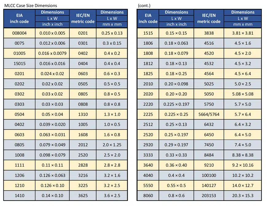
MLCC requirements fall under EIA-198. Their standardized size and shape offerings are a reflection of American EIA standards, often represented using Imperial measurements (e.g., inches) rather than Metric. When reading a specifications chart, like Figure 1, EIA dimension codes correspond with the dimensions of the MLCC itself. For example, a rectangular chip with the dimensions 0.08 inches in length by 0.05 inches in width is coded as “0805.” Looking at the chart, you’ll notice International Electrotechnical Commission/ European Standard (IEC/EN) codes too. The Joint Electron Device Engineering Council (JEDEC) established this set of specifications to represent the Metric system. See Figure 1. below with EIA inch and IEC/EN metric dimension and codes.

Common MLCC Case Size Codes
While EIA‑198 defines a wide range of MLCC case sizes, most designs use a relatively small subset of standard codes. The table below summarizes the most common EIA inch codes and their IEC/EN metric counterparts for quick reference.

EIA codeDimensions (inch)IEC/EN codeDimensions (mm)
010050.016 × 0.00804020.4 × 0.2
02010.024 × 0.01206030.6 × 0.3
04020.040 × 0.02010051.0 × 0.5
06030.060 × 0.03016081.6 × 0.8
08050.080 × 0.05020122.0 × 1.25
12060.126 × 0.06332163.2 × 1.6
12100.126 × 0.09832253.2 × 2.5

These nominal dimensions can vary slightly between manufacturers, so always refer to the specific component datasheet when finalizing footprints and clearances.

Here is expanded table with listing of more case size variants:
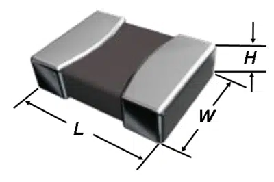

MLCC Dimensions
Figure 1. MLCC Case Size Dimensions EIA inch and IEC/EIA metric

MLCC sizes range from 008004 (0.010 inches x 0.005 inches) to 8060 (0.8 inches x 0.6 inches). Height dimensions aren’t provided in this context because height is application specific, as it depends on the number of layers in the MLCC. Layer count is determined by capacitance requirements.

Figure 2. is showing relative MLCC case size comparison of the most common case sizes.

Figure 2. Relative MLCC popular case sizes comparison

Over time, case sizes continue to run smaller and smaller. Designers are tasked with minimizing SWaP—size, weight, and power—while maintaining or increasing functionality. It’s no surprise that codes 0201 through 1206 were the most requested sizes over the last two decades, according to Paumanok Research. As time goes on, that range will likely shift downwards. It’s worth noting that the industry has seen a gradual increase in production for the 1206 and 1210 case size MLCCs. Figure 3. sourced from Murata is showing evolution of MLCC case size share with time.
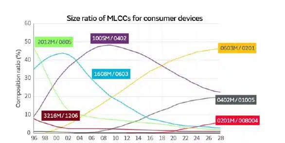
MLCC case size mix share time evolution; source: Murata

Frequently Asked Questions about MLCC Case Sizes

What are MLCC case sizes?

MLCC (Multilayer Ceramic Capacitor) case sizes define the physical dimensions of the capacitor package. They are standardized by EIA (inch-based codes like 0805) and IEC/EN (metric-based codes) to ensure compatibility across manufacturers.

Why are MLCC case size standards important?

Standards ensure interchangeability, simplify design, and support global supply chains. They allow engineers to select components that fit precise board layouts while maintaining electrical performance.

What is the difference between EIA and IEC/EN codes?

EIA codes use imperial dimensions (e.g., 0805 = 0.08 x 0.05 inches), while IEC/EN codes use metric equivalents. Both systems describe the same physical sizes but in different units.

Which MLCC case sizes are most common?

The most widely used case sizes are 0201 through 1206. These sizes balance miniaturization with performance and are heavily used in consumer electronics, automotive, and industrial applications.

How are MLCC sizes evolving?

Over time, MLCCs are trending toward smaller case sizes to reduce size, weight, and power (SWaP) while increasing functionality. However, demand for larger sizes like 1206 and 1210 has also grown for high-capacitance applications.

Special Case Variants and Derating

In addition to standard rectangular chips, many manufacturers offer long‑body, high‑voltage, reverse‑geometry, and soft‑termination MLCCs within the same nominal case size family. These variants use modified dimensions or terminal structures to improve surge capability, reduce equivalent series inductance (ESL), or enhance robustness against board flex and vibration. For high‑capacitance and high‑voltage applications, it is good practice to apply voltage and temperature derating that depends on both dielectric system and case size. Larger case sizes like 1206 and 1210 can support higher capacitance and voltage, but they also experience higher mechanical stress, making layout, mounting, and derating strategy critical for long‑term reliability.

How to Identify and Select the Right MLCC Case Size

  1. Understand the Standards

    Learn the difference between EIA (inch-based) and IEC/EN (metric-based) codes. For example, an 0805 MLCC measures 0.08 x 0.05 inches.

  2. Check Your PCB Layout

    Match the MLCC footprint to your printed circuit board design. Ensure pad spacing and soldering requirements align with the chosen case size.

  3. Consider Electrical Requirements

    Select a case size that supports the required capacitance and voltage rating. Larger case sizes often allow higher capacitance values.

  4. Balance Size, Weight, and Power (SWaP)

    For compact devices, choose smaller case sizes like 0201 or 0402. For power or automotive applications, larger sizes like 1206 may be more needed but watch for higher vibration sensitivity. Check flexible termination options and reverse geometry types to increase vibration robustness, lower ESL and better power dissipation.

  5. Verify Land Pattern and Assembly Conditions

    Confirm that your PCB footprint follows vendor or IPC recommendations for the selected case size, including pad dimensions, solder mask, and stencil design, especially for 0402 and smaller sizes. This reduces tombstoning risk and improves long‑term mechanical reliability.


Related

Source: Prepared using source from Knowles Precision Devices Blog

Recent Posts

Illustration of a thin-film capacitor stack with TiN electrodes and an ultrathin hafnium zirconium oxide ferroelectric layer on silicon

Sub-Volt Ferroelectric HZO Capacitor Pairs Speed and Endurance

6.11.2026
3
Cut-open lithium-ion capacitor pouch cell showing stacked carbon electrodes and separators, with vials of carbon powder

Lithium-Ion Capacitor Review Backs Hard Carbon//AC Pairing

6.11.2026
2
Rack power shelf in an AI data center with film DC-link capacitors, a supercapacitor bank and a converter board

800 VDC AI Data Centers Reshape Capacitor Demand for 2027

6.11.2026
2

Transformer Losses and Thermal Design: Modelling and Validation

4.11.2026
20

AI Server Power Supply Efficiency Under Pulsed Loads

4.11.2026
11
Würth Elektronik ICS PowerBusbar PF vertical PCB busbars with flat metal bodies and press-fit pins.

Würth PowerBusbar PF: Vertical Press-Fit Busbars for PCBs

4.11.2026
24
Würth Elektronik WE-LHMI and WE-HCI power inductor comparison slide showing current ratings and maximum operating temperatures

Power Inductor Selection: Ferrite vs Powder Core Trade-Offs, Würth Elektronik Webinar

3.11.2026
34
Conceptual polypropylene DC-link film capacitor module with parallel cells and copper interconnections

DC-Link Film Capacitor Modules: Inductance and Thermal Design, Jianghai-Europe Tech Memo

3.11.2026
29

Motor Run Capacitor Safety Classes S0–S3: A Design Guide

2.11.2026
27

Upcoming Events

Nov 24
16:00 - 17:00 CET

Select the Correct Components for Your DC/DC Converter

Dec 1
16:00 - 17:00 CET

Developing low-noise mixed-signal systems

Dec 8
16:00 - 17:00 CET

WE-CCMF: Design Principles, Layout Guidelines and Measurement Results for High-Speed EMI Filtering

View Calendar

Popular Posts

  • Buck Converter Design and Calculation

    0 shares
    Share 0 Tweet 0
  • September 2026 Interconnect, Passives and Electromechanical Components Market Insights

    0 shares
    Share 0 Tweet 0
  • Boost Converter Design and Calculation

    0 shares
    Share 0 Tweet 0
  • LLC Resonant Converter Design and Calculation

    0 shares
    Share 0 Tweet 0
  • Capacitor Charging and Discharging

    0 shares
    Share 0 Tweet 0
  • RF Connector Types: How To Choose the Right One

    0 shares
    Share 0 Tweet 0
  • Flyback Converter Design and Calculation

    0 shares
    Share 0 Tweet 0
  • Passive Low Pass Filters: Fundamentals and EMI Design

    0 shares
    Share 0 Tweet 0
  • Audio Capacitors: Choosing Capacitors for Crossover Circuits

    0 shares
    Share 0 Tweet 0
  • MLCC and Ceramic Capacitors

    0 shares
    Share 0 Tweet 0

Newsletter Subscription


Passive Components Blog

© 2015–2026
All rights reserved

  • Home
  • Privacy Policy
  • EPCI Membership & Advertisement
  • About

No Result
View All Result
  • Home
  • Knowledge Blog
  • Dossiers
  • PCNS

© 2015–2026
All rights reserved