Passive Components Blog
No Result
View All Result
  • Home
  • News
    • All
    • Aerospace & Defence
    • Antenna
    • Applications
    • Automotive
    • Capacitors
    • Circuit Protection Devices
    • electro-mechanical news
    • Filters
    • Fuses
    • Inductors
    • Industrial
    • Integrated Passives
    • inter-connect news
    • Market & Supply Chain
    • Market Insights
    • Medical
    • Modelling and Simulation
    • New Materials & Supply
    • New Technologies
    • Non-linear Passives
    • Optoelectronics and Isolation
    • Oscillators
    • Passive Sensors News
    • Resistors
    • RF & Microwave
    • Telecommunication
    • Weekly Digest
    Littelfuse TP7.0SMD-XC automotive TVS diodes with black surface-mount bodies and silver end terminals.

    Littelfuse Introduces Extremely Low Clamping Voltage TVS Diodes for Automotive Protection

    Supercapacitor LSM production

    LS Materials Wins $51.5M AI Data Center Supercapacitor Order

    Features of BCZT and strontium titanate dielectric layers in a thin-film superlattice

    Relaxor superlattice capacitors approach 99% efficiency

    Stackpole RMAN thick-film chip resistors with rectangular bodies and metal end terminations

    Stackpole 2512 AlN Thick-Film Resistors Rated up to 3.5 W

    ECIA September 2026 Industry Pulse electronic component trends and sentiment report

    ECIA September 2026 Pulse: Growth Holds, Supply Pressure Persists

    Wk 39 Electronics Supply Chain Digest

    Concept illustration of TT Electronics resistor and sensing technologies with chip resistors, a shaft potentiometer and a slotted optical sensor

    TT Electronics: Resistor and Sensing Trends at electronica 2026

    Conceptual Toray heat-resistant film capacitor beside an inverter cooling structure.

    Toray Film Capacitor Enables 150°C Inverter Operation

    Silicon capacitors and integrated passives dossier cover

    Silicon Capacitors and Integrated Passives Dossier Report 10/26

    Trending Tags

    • Ripple Current
    • RF
    • Leakage Current
    • Tantalum vs Ceramic
    • Snubber
    • Low ESR
    • Feedthrough
    • Derating
    • Dielectric Constant
    • New Products
    • Market Reports
  • Knowledge Blog
  • Dossiers
    • Aerospace and Defense Passive Components Dossier
    • AI Hardware Dossier
    • Automotive Dossier
    • Industrial Robotics Dossier
    • Power Converter Dossier
    • Capacitor Dossier
    • Circuit Protection Dossier
    • Inductor Dossier
    • Resistor Dossier
    • Silicon Capacitors and Integrated Passives Dossier
  • Suppliers
    • Who is Who
  • PCNS
    • PCNS 2025
    • PCNS 2023
    • PCNS 2021
    • PCNS 2019
    • PCNS 2017
  • Events
  • Home
  • News
    • All
    • Aerospace & Defence
    • Antenna
    • Applications
    • Automotive
    • Capacitors
    • Circuit Protection Devices
    • electro-mechanical news
    • Filters
    • Fuses
    • Inductors
    • Industrial
    • Integrated Passives
    • inter-connect news
    • Market & Supply Chain
    • Market Insights
    • Medical
    • Modelling and Simulation
    • New Materials & Supply
    • New Technologies
    • Non-linear Passives
    • Optoelectronics and Isolation
    • Oscillators
    • Passive Sensors News
    • Resistors
    • RF & Microwave
    • Telecommunication
    • Weekly Digest
    Littelfuse TP7.0SMD-XC automotive TVS diodes with black surface-mount bodies and silver end terminals.

    Littelfuse Introduces Extremely Low Clamping Voltage TVS Diodes for Automotive Protection

    Supercapacitor LSM production

    LS Materials Wins $51.5M AI Data Center Supercapacitor Order

    Features of BCZT and strontium titanate dielectric layers in a thin-film superlattice

    Relaxor superlattice capacitors approach 99% efficiency

    Stackpole RMAN thick-film chip resistors with rectangular bodies and metal end terminations

    Stackpole 2512 AlN Thick-Film Resistors Rated up to 3.5 W

    ECIA September 2026 Industry Pulse electronic component trends and sentiment report

    ECIA September 2026 Pulse: Growth Holds, Supply Pressure Persists

    Wk 39 Electronics Supply Chain Digest

    Concept illustration of TT Electronics resistor and sensing technologies with chip resistors, a shaft potentiometer and a slotted optical sensor

    TT Electronics: Resistor and Sensing Trends at electronica 2026

    Conceptual Toray heat-resistant film capacitor beside an inverter cooling structure.

    Toray Film Capacitor Enables 150°C Inverter Operation

    Silicon capacitors and integrated passives dossier cover

    Silicon Capacitors and Integrated Passives Dossier Report 10/26

    Trending Tags

    • Ripple Current
    • RF
    • Leakage Current
    • Tantalum vs Ceramic
    • Snubber
    • Low ESR
    • Feedthrough
    • Derating
    • Dielectric Constant
    • New Products
    • Market Reports
  • Knowledge Blog
  • Dossiers
    • Aerospace and Defense Passive Components Dossier
    • AI Hardware Dossier
    • Automotive Dossier
    • Industrial Robotics Dossier
    • Power Converter Dossier
    • Capacitor Dossier
    • Circuit Protection Dossier
    • Inductor Dossier
    • Resistor Dossier
    • Silicon Capacitors and Integrated Passives Dossier
  • Suppliers
    • Who is Who
  • PCNS
    • PCNS 2025
    • PCNS 2023
    • PCNS 2021
    • PCNS 2019
    • PCNS 2017
  • Events
No Result
View All Result
Passive Components Blog
No Result
View All Result

3-Phase EMI Filter Design, Simulation, Calculation and Test

22.5.2026
Reading Time: 17 mins read
A A

This presentation from Würth Elektronik by Andreas Nadle provides an in-depth walkthrough for designing, simulating, and validating 3-phase EMI filters based on real EMC signatures of a device under test (DUT).

Introduction

3-phase AC/DC power conversion is fundamental to modern industrial applications, yet it comes with challenges—particularly electromagnetic interference (EMI) that can degrade system performance and regulatory compliance.

This presentation provides a comprehensive guide to designing, simulating, and validating 3-phase input EMI / EMC filters using state-of-the-art digital tools and real measurement data. Designed for engineers and technical specialists, the article distills essential steps from interference basics through component selection to laboratory validation.

The design of 3-phase EMI filters—filtering both common-mode (CM) and differential-mode (DM) interference—requires a systematic approach that combines theoretical analysis, simulation, and experimental validation.

Key Takeaways

  • This article provides a comprehensive guide for designing, simulating, and validating 3-phase EMI filters.
  • Key topics include the origins of noise, component selection, and optimization for regulatory compliance.
  • It emphasizes the importance of using X and Y capacitors for differential and common mode noise suppression.
  • Engineers can utilize digital tools and real measurement data to ensure robust performance.
  • The presentation includes practical steps for filter design, testing, and layout considerations.

Chapter 1: Basics of Interference in 3-Phase Systems
1.1 Differential Mode vs Common Mode Currents

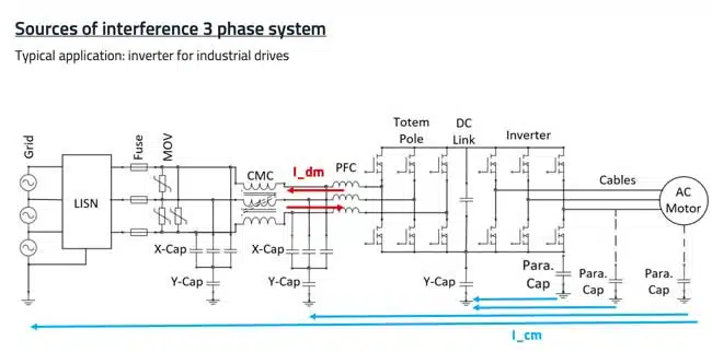
– Differential Mode (DM): Currents follow intended circuit paths, are easier to trace, and generally higher amplitude.
– Common Mode (CM): Currents flow via parasitic paths, affecting unintended circuit segments and are a major source of radiated EMI.

ModePathCurrent magnitudeFilteringMain cause
DifferentialWithin circuitHighLC, π, T TopologydI/dt (current switching)
CommonParasitic/earthLow (µA)CMC, Y-capacitorsdU/dt (voltage surges)

1.2 Application Example: Industrial Drives

Inverters for industrial drives are prime examples, with high switching frequencies and power levels that exacerbate EMI concerns.

Chapter 2: Filter Components and Selection
2.1 Safety Capacitors: Y2, X2, MLCC, and Film

Safety capacitors reduce EMI by providing paths for high-frequency currents. Their classification (X2, Y2) dictates voltage, failure mode, and use location.

  • X Capacitors: Connected between phases (line-to-line). They suppress differential mode (DM) noise. X1 capacitors are rated for higher surge voltages (up to 5 kV), while X2 capacitors are smaller and cheaper but limited to 2.5 kV surges.
  • Y Capacitors: Connected between phase and protective earth. They suppress common mode (CM) noise. Their value is limited by leakage current regulations (typically < 4.7 nF per line in industrial systems).
TypeApplicationAdvantagesLimitations
X CapacitorsPhase-to-phase filteringHigh surge capabilityLarger size, higher cost
Y CapacitorsPhase-to-earth filteringExcellent high-frequency suppressionLeakage current limitations

Engineers must balance capacitance value, safety ratings, and leakage current. Film capacitors are robust but bulky, while MLCCs (multi-layer ceramic capacitors) offer excellent high-frequency performance but limited capacitance.

  • Y2 Capacitors (Phase-to-Protective Earth):
    • WCAP-FTY2: Pitch 10–37.5mm, 330VAC, 1nF–1µF, -40°C/+110°C
    • WCAP-CSSA (MLCC Y2): SMD 1808–2220, 250VAC, 33pF–4.7nF, -55°C/+125°C
    Y2 MLCCs used for compact or SMT designs. MKP Film capacitors available for higher capacitance.
  • X2 Capacitors (Phase-to-Phase):
    • WCAP-FTX2/FTXX: Pitch 7.5–37.5mm, 310VAC/275VAC, 5.6nF–6.8µF, -40°C/+105°C
    • WCAP-FTXH: Pitch 15–37.5mm, 310VAC, 33nF–10µF, up to +110°C, THB 1000h @ 85°C 85%
    Film capacitors dominate for bulk energy storage in X2 position; MLCC for high-frequency bypass.
TypeKey SeriesVolt. (Vrms)Capacitance RangeTemp. Range
Y2 – Film/MLCCWCAP-FTY2, WCAP-CSSA250–33033pF–1µF-55 to +125°C
X2 – Film/MLCCWCAP-FTX2, FTXH275–3105.6nF–10µF-40 to +110°C

2.2 Common Mode Chokes (CMCs)

Common mode chokes (CMCs) provide inductance to attenuate CM currents. Their performance depends on core material:

Core MaterialFrequency RangeAdvantagesLimitations
Manganese-Zinc FerriteUp to ~5 MHzGood low-frequency attenuationLimited high-frequency performance
Nickel-Zinc Ferrite5–30 MHzBetter high-frequency suppressionLower permeability at low frequencies
NanocrystallineBroadband (kHz–tens of MHz)Excellent wideband performanceHigher cost, sensitive to saturation

Note: Real inductance depends on test frequency; nanocrystalline cores show substantial drop-off above 100kHz.

  • MnZn ferrite core: 1–24A, 0.52mH–12mH, 1kHz–2MHz frequency range (e.g., WE-TPB, Ø47mm)
  • Nanocrystalline core: 20–46A, up to 208mH, 1kHz–20MHz (e.g., WE-TPBHV, Ø70mm)
  • Frequency Response: Nanocrystalline offers better performance above 1MHz, but with core nonlinearity and specific derating at higher frequencies.
Core MaterialCurrent (A)Inductance (mH)Freq. Range (kHz)Example Series
MnZnto 240.52-121–2000WE-TPB
Nanocrystallineto 460.2–2081–20000WE-TPBHV

2.3 Surge Protection Varistors

Varistors protect against voltage surges. Selection is based on voltage class, current capacity, certified reliability.

  • WE-VD Series: 5–20mm diameter, 14V–1000V RMS, 100A–10,000A, -40°C to +105°C, certified by UL/IEC/VDE.

2.4 Component Selection Example: Lab Device Under Test (DUT)

  • Filter for 4kW inverter drive, 5A, 400V 3-phase grid
  • Combination: Y2 MLCC caps, X2 film caps, nanocrystalline CMC, WE-VD varistor

Chapter 3: Filter Topology, Calculation and Simulation

3.1 Detailed Filter Structures

CM and DM Filtering Structure:
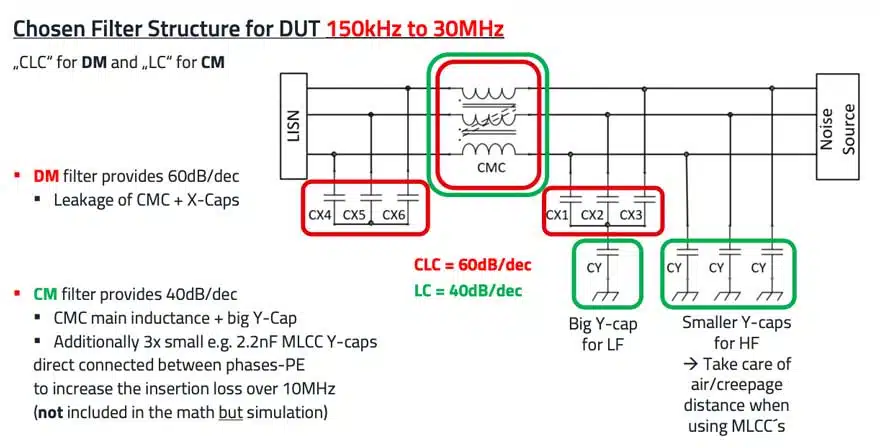
  • CM (Common Mode): LC topology (CMC + large Y-capacitor)
  • DM (Differential Mode): CLC π topology (3 x X2 between each phase, 2 x series CMCs)
  • High-frequency suppression: 3x small MLCC Y2-caps between each phase and PE supplement the main Y-cap
Functional BlockMain PartsPurpose
CM FilterCMC + large Y-capSuppress parasitic return-path currents
DM FilterX2 film caps + series CMCsSmooth line-to-line switching noise
Surge ProtectionVaristor (WE-VD)Clamp surges, protect filter/downgrid

3.2 Component Sizing and Calculations

Key variables:
– fc = corner frequency
– Ldm, Lcm = DM/CM inductance
– Cx, Cy = interphase and PE capacitance
– Required attenuation = 60dB at 200kHz as specified by CISPR B

Effective X2 Capacitance (Cx) Between Phases:

C xeff = 1 1Cx1 + 1Cx2

Effective Y2 Capacitance (Cy), phase-to-PE:

C yeff = ( 1Cy1 + 1Cy2 + 1Cy3 + 1Cy4 ) –1

Corner Frequency (DM or CM):

f cdm/cm = 1 2 π L ⁢ C

Required Attenuation for Desired Frequency at 1-stage LC:

A fsw = log fsw / f co ⋅ 40 dB

Required Attenuation for Desired Frequency at 2-stage LC:

RelatedPosts

Würth Elektronik Previews Components, PCBs and Power Solutions at electronica 2026

Würth Elektronik Updates REDEXPERT DC‑DC Converter Designer

Würth Elektronik Coupled Inductors Harnessing Leakage Inductance in SEPIC, ZETA and Ćuk Converters

A fsw = log fsw / f co ⋅ 80 dB

CLC Filter PI Attenuation:

A fsw = log fsw / f co ⋅ 60 dB

Attenuation:
For DM CLC: 60dB/dec
For CM LC: 40dB/dec

Example Sizing (referenced):
– fc_dm = 20kHz (DM), fc_cm = 6.3kHz (CM)
– Cx = 4.7µF x 6, Cy = 47nF, Lcm = 8.4mH, Ldm ≈ 62µH

3.3 Simulation – Practical Details

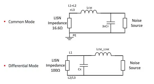
  • LTspice used for transfer function analysis (frequency-dependent insertion loss)
  • Cores exhibit non-linear impedance: E.g., 8mH @10kHz, ~5mH @100kHz for nanocrystalline cores
  • Verify physical layout in Altium: PCB shows capacitors and CMC placement, improved PE paths

Chapter 4: Test Setup and Practical Measurements

4.1 Laboratory Measurement Configuration

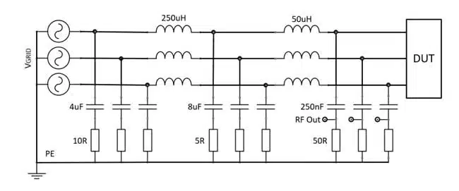
  • Standard LISN (Line Impedance Stabilization Network) as per CISPR 16, 3-phase version
  • Test device: 4kW inverter fed by 400V 3-phase, driving a 5A motor load (fan)
  • Test setup incorporates LISN, inverter + EMC filter, and realistic load
  • Test frequency range: 150kHz to 30MHz

4.2 EMI Measurement Results

ConfigurationMeasured EMI (dBµV)Comment
No Filter115Well above Class B limit (65 dBµV QP)
Filter, Correct Ycap Placement~55Passes; 60dB attenuation @200kHz
Filter, Ycap Misplacement~>65Fails; Misplacement reduces performance
  • DM noise dominates below 50kHz, CM above 100kHz
  • Correct Y-capacitor position is critical for high-frequency attenuation
  • Measurement probes compare total CM vs DM noise for full compliance validation

Chapter 5: PCB Design, Manufacturing, and Optimization

5.1 PCB Layout & Mechanical Considerations

  • Use 4-layer PCBs with separated high-current and signal layers for best EMC
  • Ensure low impedance path from PE to chassis; improve ground plane connectivity
  • Air and creepage distances must comply—especially when using MLCC Y capacitors
  • Compact layout helps minimize parasitic couplings and optimizes cooling

5.2 Troubleshooting and Field Failures

  • Improper placement of filter components (Ycaps, CMC) can negate up to 40dB attenuation
  • Varistor failure: always verify with high-energy test pulses as per IEC/UL
  • Frequency response of CMC may lead to excessive EMI above 1–2MHz—redesign or parallel chokes as remedy

5.3 Recommendations and Final Optimization Steps

  • Use simulation to predict worst-case—verify with real EMI data
  • Select capacitors with stress test data (THB, temperature cycling, surge)
  • Document and peer-review PCB layout for high-voltage safety
  • Iterate design as new EMI problems emerge in the field

Conclusion

A modern 3-phase input EMI filter must be engineered with deep understanding of system interference sources, smart component selection, and rigorous verification via simulation and measurement. The combined approach outlined here delivers robust designs that meet stringent EMC standards in real-world industrial environments.

FAQ: 3-Phase EMI Filter Design & Simulation

What is the role of X and Y capacitors in EMI filters?

X capacitors are used between phases to suppress differential mode noise, while Y capacitors connect between phase and earth to suppress common mode noise. Both are essential for comprehensive EMI filtering.

Why are common mode chokes important in three-phase systems?

Common mode chokes attenuate currents returning through protective earth. Their performance depends on core material, with nanocrystalline cores offering wideband suppression and ferrites providing targeted frequency attenuation.

What is the difference between differential mode and common mode interference?

Differential mode interference flows between phase conductors, while common mode interference returns through protective earth. Each requires different filtering strategies.

How does LTSpice help in EMI filter design?

LTSpice allows engineers to simulate both differential and common mode noise paths using LISN impedance models. This predicts insertion loss and ensures the filter meets EMC requirements before physical prototyping.

What are best practices for PCB layout in EMI filters?

Critical practices include placing Y capacitors close to the noise source, using wide copper planes for grounding, minimizing parasitic inductance, and considering multi-stage filters for improved high-frequency performance.

How important is PCB layout in EMI filter design?

PCB layout is critical. Incorrect placement of Y capacitors or poor grounding can reduce attenuation by tens of decibels.

How-to: Design and Validate a 3-Phase EMI Filter

  1. Measure Baseline EMI

    Perform initial measurements without filters to determine the required attenuation margin.

  2. Select Capacitors

    Choose X capacitors for differential mode suppression and Y capacitors for common mode suppression, balancing capacitance, leakage current, and surge ratings.

  3. Choose Common Mode Choke

    Select choke material based on frequency range. Manganese-zinc ferrites are effective at low frequencies, while nanocrystalline cores provide wideband performance.

  4. Simulate in LTSpice

    Model DM and CM paths using LISN impedance values. Ensure simulated insertion loss meets or exceeds 60 dB at critical frequencies.

  5. Validate in EMC Laboratory

    Test the filter across 150 kHz–30 MHz using a certified chamber and LISN setup. Compare results with simulation data.

  6. Optimize PCB Layout

    Place Y capacitors near the noise source, minimize trace lengths, and use direct grounding paths. Consider multi-stage filters for enhanced performance.

  7. Finalize Design

    Adjust component values or add stages if necessary. Ensure compliance with EMC standards and robustness under real-world operating conditions.

Related

Source: Würth Elektronik

Recent Posts

Supercapacitor LSM production

LS Materials Wins $51.5M AI Data Center Supercapacitor Order

13.10.2026
14
Features of BCZT and strontium titanate dielectric layers in a thin-film superlattice

Relaxor superlattice capacitors approach 99% efficiency

12.10.2026
10
Conceptual Toray heat-resistant film capacitor beside an inverter cooling structure.

Toray Film Capacitor Enables 150°C Inverter Operation

9.10.2026
21
Silicon capacitors and integrated passives dossier cover

Silicon Capacitors and Integrated Passives Dossier Report 10/26

8.10.2026
39
Panasonic Industry PGS graphite heat-spreading technology and passive components for spacecraft thermal management

Panasonic Targets Space Thermal Design at SPCD 2026

8.10.2026
26
tungsten-bronze-ceramic-capacitor-stack

Tungsten bronze capacitors combine high κ and thermal stability

7.10.2026
27
Datasheet-style illustration of a TDK MLJ1608-G multilayer chip inductor with end terminals

TDK Expands1608 Inductors for Automotive PoC Filters

6.10.2026
11
Ruggedized passive component customization overview covering capacitors, resistors and inductors.

Ruggedized Passive Components: Reliability Beyond the Datasheet

6.10.2026
38
YAGEO Group PMT6709NLT and PHT7249NLT GDSC SMD LLC gate-drive transformers for SiC and GaN switching applications

YAGEO Introduces LLC Transformers for SiC and GaN Gate Drives

2.10.2026
34

Upcoming Events

Oct 14
17:00 - 18:00 CEST

Live Demo! Discover KYOCERA AVX Antenna Integrator Studio (AIS)

Oct 19
15:00 - 16:00 CEST

ESCC-qualified Pt Temperature Sensors for Space Applications

Oct 27
15:00 - 16:00 CET

Heraeus Electronics Webinar: What materials perform when failure is not an option?

View Calendar

Popular Posts

  • Buck Converter Design and Calculation

    0 shares
    Share 0 Tweet 0
  • Boost Converter Design and Calculation

    0 shares
    Share 0 Tweet 0
  • LLC Resonant Converter Design and Calculation

    0 shares
    Share 0 Tweet 0
  • Flyback Converter Design and Calculation

    0 shares
    Share 0 Tweet 0
  • Capacitor Charging and Discharging

    0 shares
    Share 0 Tweet 0
  • Audio Capacitors: Choosing Capacitors for Crossover Circuits

    0 shares
    Share 0 Tweet 0
  • MLCC and Ceramic Capacitors

    0 shares
    Share 0 Tweet 0
  • Resistor Symbols

    0 shares
    Share 0 Tweet 0
  • Thermistors Basics, NTC and PTC Thermistors

    0 shares
    Share 0 Tweet 0
  • RF Connector Types: How To Choose the Right One

    0 shares
    Share 0 Tweet 0

Newsletter Subscription


Passive Components Blog

© 2015–2026
All rights reserved

  • Home
  • Privacy Policy
  • EPCI Membership & Advertisement
  • About

No Result
View All Result
  • Home
  • Knowledge Blog
  • Dossiers
  • PCNS

© 2015–2026
All rights reserved