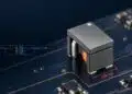
This presentation from Würth Elektronik by Lorandt Fölkel provides selection guide of use of ferrite beads for filtering application with practical case study in a 100W buck-boost converter as a noise source.
The presentation provides details about 3 different design concepts using almost the same BOM (bill of material) but different layout to achieve the EMC requirements as well conducted and radiated emissions.
Key Takeaways
- Ferrite bead selection is vital for effective EMI suppression in electronics.
- Engineers must consider impedance, rated current, and application-specific needs when choosing ferrite beads.
- Ferrite beads convert high-frequency noise into heat, making them crucial for maintaining signal integrity.
- A multi-step workflow helps in selecting the right ferrite bead based on noise characteristics and thermal ratings.
- Thorough testing and validation against EMC standards ensure reliable performance in electronic systems.
Introduction
The last cars without electronic have been built in the sixties, since that time the electronic devices invade the cars. Started from a simple AM/FM Radio until today where autonomous driving and talking to the driver becomes standard for next generation cars. However already the in the early sixties the manufacturers was facing EMI (electro-magnetic-interferences) generated from the ignition coils and interfere with radio reception.
The “magic” solution to cancel the noise was to use a rod core inductor to filter those sparks generated RF harmonics. Later in the nineties, the cell phones boom was the one who made interferences with the audio systems generating unwanted sound. Today the noise sources is almost impossible to avoid and should be considered already in the early design stage. Therefore, is need to know the harmonics generated and to be filtered close as possible to the noise source. As well, the signals must be immune to interferences to avoid fails at the final EMC testing of the car.
Electromagnetic interference (EMI) suppression is a critical design consideration in modern electronic systems. Ferrite beads, also known as EMI suppression beads, are passive components that provide frequency-dependent impedance to attenuate unwanted high-frequency noise while allowing low-frequency signals and DC to pass. Selecting the correct ferrite bead requires balancing electrical performance, package constraints, and system-level requirements.
Chapter 1: Fundamentals of Ferrite Beads
Ferrite beads are constructed from ferrite material, a ceramic compound with high magnetic permeability. At low frequencies, the bead behaves like a simple inductor. At higher frequencies, however, the ferrite material introduces losses, converting high-frequency noise into heat. This makes ferrite beads particularly effective for EMI suppression in power supply lines and signal traces.
Chapter 2: Key Electrical Parameters
When selecting a ferrite bead, engineers must evaluate several parameters:
| Parameter | Description | Design Impact |
|---|---|---|
| Impedance (Z) | Frequency-dependent resistance to AC signals | Defines noise attenuation capability |
| DC Resistance (DCR) | Resistance at DC | Affects power loss and efficiency |
| Rated Current | Maximum continuous current without overheating | Limits applicability in power circuits |
| Self-Resonant Frequency | Frequency where inductive and capacitive reactances cancel | Defines effective operating range |
Chapter 3: Application-Specific Considerations
Ferrite beads are not one-size-fits-all components. Their effectiveness depends heavily on the application domain, the type of noise present, and the system’s operating environment. Below are expanded considerations for three major categories of use.
3.1 Digital Circuits
In high-speed digital systems, such as microcontrollers, FPGAs, and SoCs, ferrite beads are commonly placed on power supply rails to suppress switching noise. The rapid rise and fall times of digital signals generate harmonics that extend well into the hundreds of MHz. A ferrite bead with a resistive impedance peak in this frequency range is ideal. Designers often combine beads with decoupling capacitors to form a low-pass filter network, ensuring stable supply rails for sensitive ICs.
| Use Case | Noise Source | Ferrite Bead Requirement |
|---|---|---|
| Microcontroller power rails | Clock harmonics (50–300 MHz) | Bead with 100–600 Ω impedance at 100 MHz |
| Mixed-signal ICs | Cross-coupling between analog and digital domains | Bead with low DCR, moderate impedance, paired with bypass capacitors |
3.2 Automotive Electronics
Automotive environments impose stringent requirements due to wide temperature ranges, high transient currents, and strict EMC regulations. Ferrite beads used in vehicles must comply with AEC-Q200 standards and withstand temperatures from -55 °C to +150 °C. Applications include infotainment systems, battery management, and powertrain control modules. In these cases, beads must handle higher currents (up to several amperes) while maintaining stable impedance across a broad frequency spectrum.
- High-current capability (≥ 3 A continuous)
- Low DCR to minimize power loss in 12 V and 48 V systems
- Robust thermal stability for under-hood environments
- Compliance with automotive EMC standards (CISPR 25, ISO 11452)
3.3 RF and Communication Systems
In RF circuits, ferrite beads are used more selectively. While they suppress unwanted noise, they can also distort desired signals if not carefully chosen. For example, in antenna feed lines or RF front-ends, a bead with too high an impedance may attenuate the wanted signal. Therefore, RF applications often require simulation and measurement to ensure that the bead’s impedance profile aligns with the system’s frequency plan.
Typical RF use cases include:
- Preventing digital noise from coupling into RF transceivers.
- Suppressing spurious emissions in wireless modules (Bluetooth, Wi-Fi, LTE).
- Filtering supply lines of low-noise amplifiers (LNAs) without degrading gain.
Chapter 4: Practical Selection Workflow
Selecting the right ferrite bead is a multi-step process that combines theoretical analysis, datasheet evaluation, and empirical validation. Below is a detailed workflow that engineers can follow.
4.1 Define Noise Characteristics
Identify the frequency range of the unwanted noise. This can be done through spectrum analysis or by estimating harmonic content from switching frequencies. For example, a DC-DC converter switching at 2 MHz may generate harmonics up to 200 MHz.
4.2 Match Impedance Profile
Select a bead whose impedance curve peaks in the noise frequency band. The goal is to ensure that the bead presents a predominantly resistive impedance at the target frequencies, thereby dissipating noise energy rather than reflecting it.
| Noise Frequency | Recommended Impedance | Typical Applications |
|---|---|---|
| 10–50 MHz | 30–100 Ω | Switching regulators, USB 2.0 |
| 50–200 MHz | 100–600 Ω | Microcontrollers, digital buses |
| 200 MHz–1 GHz | 600–1000 Ω | RF modules, wireless systems |
4.3 Verify Current and Thermal Ratings
Ensure that the bead can handle the maximum continuous current without excessive heating. Power loss is calculated as P = I² × DCR. For high-current applications, select beads with low DCR to minimize efficiency loss.
4.4 Evaluate in Circuit
Simulation tools (e.g., SPICE models) and real-world measurements (e.g., using a spectrum analyzer or VNA) are essential to validate performance. Engineers should measure insertion loss and confirm that the bead does not introduce unwanted resonances with nearby capacitors.
4.5 Compliance and Reliability Testing
Finally, validate the design against EMC standards relevant to the application (e.g., CISPR 32 for consumer electronics, CISPR 25 for automotive). Long-term reliability testing under thermal cycling and vibration is also recommended for mission-critical systems.
By following this structured workflow, engineers can move beyond trial-and-error selection and achieve predictable, repeatable EMI suppression results.
Conclusion
Ferrite beads are indispensable components for EMI suppression in modern electronics. By carefully analyzing impedance characteristics, current handling, and application-specific constraints, engineers can ensure robust noise filtering without compromising system performance. A structured selection workflow, supported by simulation and measurement, provides the most reliable results.
Ferrite beads act as lossy inductors that provide resistive impedance at high frequencies. They convert unwanted high-frequency noise into heat, ensuring stable signal integrity in electronic systems.
ey parameters include impedance profile, DC resistance (DCR), rated current, and self-resonant frequency. These define the bead’s effectiveness in attenuating noise while maintaining efficiency.
In digital circuits, beads suppress switching noise on power rails. In automotive electronics, they must handle high currents and comply with EMC standards. In RF systems, careful selection avoids distortion of desired signals.
Simulation and real-world measurements confirm that the bead attenuates noise without introducing resonances. Compliance testing ensures designs meet EMC regulations for reliable long-term performance.
How to Select a Ferrite Bead for a Buck-Boost Converter
- Define Noise Characteristics
Identify the frequency range of unwanted noise using spectrum analysis or by estimating harmonics from switching frequencies.
- Match Impedance Profile
Select a ferrite bead whose impedance curve peaks in the noise frequency band, ensuring resistive impedance at target frequencies.
- Verify Current and Thermal Ratings
Ensure the bead can handle maximum continuous current without overheating. Minimize efficiency loss by choosing low DCR for high-current applications.
- Evaluate in Circuit
Use simulation tools and real-world measurements to validate insertion loss and confirm no unwanted resonances occur with capacitors.
- Compliance and Reliability Testing
Validate against EMC standards (e.g., CISPR 25, CISPR 32) and perform long-term reliability tests under thermal cycling and vibration.