


Source: Electronics 360, Cornell Dubilier article
by Scott Franco, director of market development, Cornell Dubilier Electronics Inc.
As prismatic aluminum electrolytics become flatter, both industrial and consumer electronics design engineers are designing-in more of these components, especially for high-voltage applications, where their energy density advantage becomes more apparent.
Aluminum electrolytic capacitors have been a mainstay in electronic power circuits for their ability to provide large bulk storage, high voltage and high energy density. However, in a growing number of applications, their on-board height has become a key limiting factor. Historically speaking, capacitors have typically been among the tallest components on the circuit board. The advent of surface-mount (SMT) capacitors, across multiple dielectric technologies, has helped to shrink the height of a loaded board. In order to achieve high capacitance or voltage using SMTs, it is often necessary to bank multiple capacitors on the PCB. Unfortunately, this approach consumes a lot of valuable board real estate, especially in applications that require high capacitance for holdup.
The fairly recent development of flat, rectangular (prismatic), aluminum electrolytic capacitors is helping circuit designers achieve low profiles, space and weight savings, especially at high application voltages.
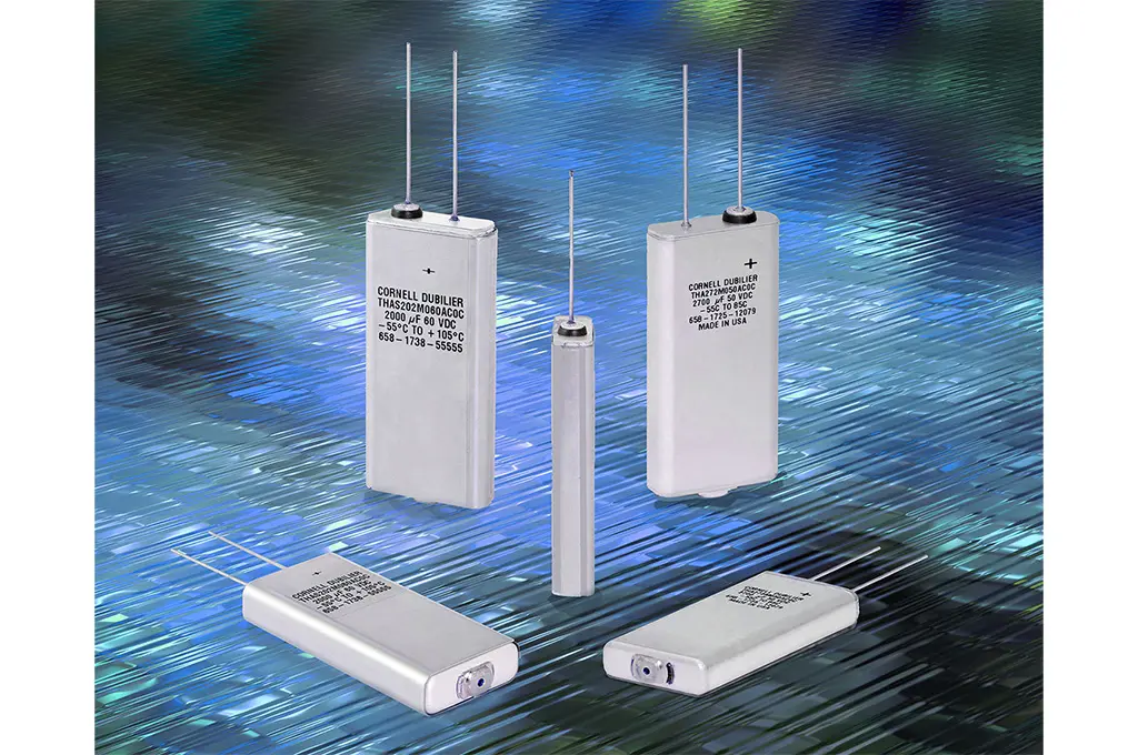
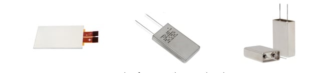 Figure 1: Examples of prismatic aluminum electrolytic capacitors.
The challenge of low profile and high energy density
While most dielectric technologies employ multilayer technology to achieve low-profile SMT chip packages, conventional aluminum electrolytics use wound capacitor elements within their SMT package types. These cylindrical windings are placed in cylindrical metal containers and mounted vertically to a rectangular mounting pad. For this reason SMT aluminum electrolytics have come to be known as V-chips, short for vertical chips.
The cylindrical packages also contain a liquid electrolyte, which must be sealed into the device. Rubber or composite seals prevent this electrolyte from escaping. This design tends to be inefficient for SMT devices, as the percentage of overall capacitor volume taken up by the seals increases as total package volume decreases. This is a key point. For typical SMT aluminum electrolytics, up to 60% of the capacitor’s volume may be space-wasting end-seal gaskets and related materials!
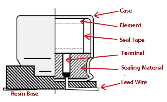 Figure 2: Cutaway diagram of typical v-chip construction, showing a high percentage of volume taken up by the seal.
Another consideration is the lifespan of the individual components. Even with quality end seals, cylindrical electrolytics gradually experience a long-term loss of electrolyte, a condition known as dry-out. Loss of electrolyte results in a corresponding loss of capacitance and increased equivalent series resistances (ESR). For that reason, conventionally sealed aluminum electrolytic capacitors have typically been limited to consumer, industrial and non-critical military and aerospace applications. For mission-critical military, aerospace and down-hole applications, circuit designers have historically specified higher-priced hermetically sealed wet-tantalum capacitors.
The solution to the historical limitations of electrolytics is to approach component construction with an entirely different device design. Prismatic aluminum electrolytic capacitors can be designed to deliver high bulk capacitance, in low profile, high energy-density packages that eliminate dry-out. This advancement is accomplished by replacing those space-wasting flexible seals with robotically laser-welded seams. The laser welds also do a far better job of preventing electrolyte loss, thus greatly extending component life. These new aluminum electrolytic package configurations allow engineers to improve reliability while saving space, weight and even loaded-board cost.
 Figure 3: Comparison of PCB real estate filled by flat CDE electrolytics (left), with SMT V-chips and tantalum caps.
Based on feedback from customers, there is a growing demand for smaller, lighter circuitry. This demand spans all market segments, pushing engineers to design circuits that either consume less power or achieve higher energy and power densities without negatively impacting reliability or material costs. While there are similar universal goals, the growing demand for electric vehicles and their charging systems is accelerating this demand curve. These applications not only require a greater number of on-board power electronics systems, but they also place high values on reliability and space efficiency.
Key metrics
Height profile
The height is measured from the board to the maximum height that the part rises above the circuit board. For SMT and radial-leaded components, the height profile is measured from the seating plane to the top of the capacitor.
Energy density
A capacitor’s energy density is typically calculated by dividing the stored energy of the capacitor by its package volume. The energy stored in a capacitor is given by: ½ C V2
The unit of stored energy is the joule, where C equals capacitance in farads and V equals maximum continuous operating voltage. The package volume is typically calculated in cubic centimeters or cubic inches. Since capacitance and voltage rating may vary with temperature, the energy density should be calculated with reference to an ambient temperature in degrees Celsius.
When comparing capacitor technologies, devices having a higher energy density store more energy per unit volume, and therefore provide the potential for on-board space savings.
Energy density of total capacitance solution
Many applications require a particular CV rating, energy holdup or ripple current for capacitors. Traditionally, the solution was to configure banks of capacitors in parallel, series or series-parallel combinations. In this scenario, the dimensional boundaries of the capacitor bank (not just the sizes of the devices) make up the total volume of the capacitor solution. The spaces between the components add considerably to the overall volume. Therefore the energy density of a bank of capacitors will always be lower than that provided by a single capacitor of the same technology.
Aluminum electrolytic design trends
Over the course of several decades, improvements in electrode foils, paper separators and electrolytes have helped to modestly shrink the size and improve the performance of cylindrical aluminum electrolytic capacitors. However, as mentioned previously, their design limitations and imperfect seals have limited conventional aluminum electrolytics to less critical applications.
Military and aerospace applications have gradually turned to prismatic and flat aluminum electrolytics for high-reliability bulk storage circuitry. They can provide space and weight savings over wet tantalum banks. In addition to their advantageous form factor, prismatic aluminum electrolytics have higher capacitance retention at -55° C when compared with wet tantalum capacitors. A good application example that demonstrates the benefits of this capability is aviation power supplies. Here, designers can achieve the bulk energy storage needed for operation at low temperatures with fewer components than alternative approaches. With their welded seams and vibration-resistant packaging, prismatic aluminum electrolytics offer the operating life and reliability needed.
As prismatic aluminum electrolytics become flatter, both industrial and consumer electronics design engineers are designing-in more of these components, especially for high-voltage applications, where their energy density advantage becomes more apparent.
Cornell Dubilier has been pioneering prismatic and flat aluminum electrolytics
Cornell Dubilier developed the first laser-welded, prismatic capacitors over 20 years ago for military and medical equipment applications. Since then, the technology has continued to evolve to span products suitable for a broad range of applications. Here is a brief snapshot of the growing family of these leading-edge devices.
THA

- THA form factor.Description: 85° C, 3,000 hour Thinpack, 8.2 mm thin, 10 g, REACH and RoHS compliant, 80K altitude, 85/85
- Temperature: -55° C to 85° C
- Voltage: 10 to 450 V DC
THAS

- THAS form factor.Description: 105° C, 3,000 hour Thinpack, 9 mm thin, 10 g, REACH and RoHS compliant, 80K altitude, 85/85 THB tested
- Temperature: -55° C to 105 ºC at ≤V DC; -40° C to 105 ºC at ≥350 V DC
- Voltage: 10 to 450 V DC
MLSH

- THAS form factor.Description: 125° C hermetic aluminum electrolytic slim pack, 80 g, 80K altitude, volume-constrained conditions
- Temperature: -55° C to 125° C
- Voltage: 30 to 250 V DC
MLSG

- Description: 125° C, 5,000 hour, stainless steel flatpack, 50 g, 80K altitude, longest life under rated conditions
- Temperature: -55° C to 125° C
- Voltage: 20 to 225 V DC
MLSG-S

- MLSG-S form factor. Description: 125° C, 5,000 hour, stainless steel slimpack, 80 g, 80K altitude, volume-constrained conditions
- Temperature: -55° C to 125° C
- Voltage: 10 to 250 V DC
MLP

- MLP form factor.Aluminum case, 85° C, 10 g, 80K altitude, long life
- Temperature: -55° C to 85° C at ≤250 V DC; -40° C to 85° C at ≥300 V DC
- Voltage: 7.5 to 420 V DC
Challenges
When a single prismatic aluminum electrolytic capacitor is being considered in lieu of a bank of alternative capacitors, attention must be paid to not exceed its ripple current rating.
Today’s flat prismatic aluminum electrolytics are best applied in applications where low profile, high bulk storage is needed, and where ripple current demands are low. To expand their use into very high ripple-current applications, prismatic electrolytic capacitors of the future will need to introduce low-loss technologies to reduce their self-heating.


