


source: Microwave & RF news
Miniature ceramic capacitors for surface-mount applications on PCBs are often available in single- and multiple-layer versions—but why use one type or the other?
Jack Browne | Sep 06, 2017
Capacitors are one of the true “building-block” components of circuit design, along with resistors and inductors. They come in many shapes and sizes, in fixed and variable capacitance values, with tiny capacitors based on ceramic dielectric materials among the most popular for printed-circuit-board (PCB) applications.
Both single-layer and multilayer ceramic capacitors are commonly used in RF/microwave circuits, attractive for their small size for use in surface-mount electronic designs. The two types of ceramic capacitors are often available from the same manufacturer, which begs the question:
Why use one type or the other? And what are the differences between them? Let’s find out.
All capacitors are charge-storing components based on at least two electrical conductors or plates separated by some form of dielectric insulating material. For any capacitor, the amount of charge per amount of applied voltage is a function of the area of the plates, the characteristics of the dielectric material, and the distance between the plates. The capacitance for a capacitor formed with two conducting plates is simply
C = εA/d
where
ε = the permittivity of the dielectric material,
A = the area of the plates, and
d = the separation distance of the plates.
The voltage potential between the plates is a function of the dielectric material and the distance between the plates, and is usually described by a parameter known as working DC voltage, or WVDC. The energy, E, that can be stored in a capacitor, is related to its capacitance value and the applied voltage:
E = (CV2)/2
where
E = the energy (in J or W/s),
C = the capacitance (in F), and
V = the applied voltage (in V).
An ideal capacitor would store all energy in the dielectric material; in real-world capacitors, however, some energy is lost due to some loss due to the equivalent series resistance (ESR) of the capacitor. Higher ESR values translate into higher amounts of loss for a capacitor. The ESR for a capacitor is usually listed in Ω with respect to a particular operating frequency.
The amount of energy that a capacitor can store is indicated by its quality factor (Q). Capacitors with lower ESR values exhibit higher Q values, also specified at a particular operating frequency. The reciprocal of Q, 1/Q, is also known as the dissipation factor or loss tangent of a capacitor and its dielectric material. Usually given as a percentage, it indicates that portion of the total power in a capacitor that is dissipated or lost as heat.
The greatest number of capacitors used in modern electronic circuits are fabricated as passive components in integrated circuits (ICs), although discrete-component capacitors are still required in large numbers for PCB applications. Many of these are in surface-mount-technology (SMT) form when used for large-volume applications produced by automated manufacturing processes, such as tape-and-reel components being fed to robotic pick-and-place machines.
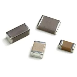
Ceramic materials are the most widely used dielectrics in modern discrete capacitors, with ceramic dielectric material providing insulation layers for a wide range of both single-layer ceramic capacitors (SLCCs) and multilayer ceramic capacitors (MLCCs). While the majority of ceramic capacitors for PCB mounting are in unpolarized leadless chip form for ease of surface mounting (Fig. 1), many different ceramic materials are also used in many sizes of ceramic disk capacitors, which are polarized with leads.

Fig. 1. Thin film porcelain and ceramic dielectric materials provide the insulators in many different types of single-layer and multilayer capacitors. Source: American Technical Ceramics
As the name suggests, SLCCs are typically formed monolithically, with a single thin ceramic layer plated with conductive electrode material on both sides and with plated connection points on top and bottom. These miniature, low-profile capacitors (Fig. 1) are available in a wide range of capacitance values, although voltage ratings are usually limited because of the small chip sizes.
An MLCC is formed with alternating layers of conductors and dielectric insulating layers, resulting in a structure that is the equivalent of a number of single-layer capacitors connected in parallel. This in turn results in an increased capacitance value for an increase in component height. Because of the construction and configuration, a MLCC is capable of higher capacitance with reduced loss and parasitic inductance compared to a SLCC, with the tradeoff being in slightly larger size and height than a SLCC. For high-frequency circuits that require relatively large current-carrying capacity, MLCCs provide excellent performance in small package sizes.
Ceramic capacitors are divided into two stability classes: Class 1, with high stability and compensation for the effects of temperature; and Class 2, with high value of capacitance per volume (high volumetric efficiency) as typically needed for higher-power applications, but with less stability with temperature and other factors than Class 1 capacitors.

Fig. 2. SLCCs are available in a wide range of sizes and capacitance values. Source: Johanson Technology
Comparing Components
How do SLCCs and MLCCs compare in terms of basic characteristics and performance levels? A sampling of a leading supplier’s SLCC and MLCC product lines may shed some light on the differences between the two types of ceramic capacitors. For example, American Technical Ceramics offers both SLCCs and MLCCs, available as negative-positive 0 ppm/°C (NPO) components with zero shift in capacitance as a function of temperature. This translates into very predictable temperature coefficients for these capacitors, with extremely flat capacitance across wide temperature ranges. Both types of capacitors are also available with high Q values and low dissipation losses.
The SLCCs are usable at frequencies to 100 GHz, covering a total capacitance range of 0.04 to 10,000 pF depending upon package size and voltage ratings to 100 WVDC. The electrical performance of any series of SLCCs is dependent upon the type of ceramic insulator material and its dielectric constant (Dk), which includes insulator materials with extremely high Dk (to 25,000) to achieve the highest capacitance values.
For example, the company’s ATC 116 series Microcap SLCCs offer typical capacitance values of 0.06 to 220 pF in square-sided chip capacitors measuring 0.015 × 0.015 in. (0.381 × 0.381 mm), and larger models [0.090 × 0.090 in. (2.29 × 2.29 mm)] available with capacitances as high as 6200 pF. The maximum dissipation factor at 1 kHz is 2.5%.

Fig. 3. MLCCs are shown next to a scale with 0.5-mm increments. Source: Kyocera
The same company’s 700A and 700B Series of porcelain and ceramic multilayer capacitors also provide the temperature-stable characteristics of NPO dielectric materials in multilayer configurations. The smaller 700A Series capacitors measure 0.055 × 0.055 in. with capacitance values of 0.1 to 1000 pF; they are rated for WVDC to 250 V dc. The Q is greater than 10,000 for capacitance values to 110 pF and greater than 2000 for capacitance values above 110 pF. The twice-as-large 700B Series capacitors measure 0.110 × 0.110 in. with available capacitance values of 0.1 to 5100 pF and WVDC rating of 1,500 V dc. The Q is greater than 10,000 for capacitance values to 220 pF and greater than 2,000 for capacitance values above 220 pF.
Several series of MLCCs from AVX are also based on NPO dielectric materials, featuring excellent capacitance stability as a function of temperature. All of the MLCCs are rated for WVDC of 200 V dc or more and temperature coefficient of capacitance (TCC) of ±30 ppm/ºC or better. The Series 600L capacitors have capacitance values of 0.1 to 27.0 pF in a case size of 0.04 × 0.02 in. (1.02 × 0.51 mm), while the Series 600F MLCCs cover a capacitance range of 0.1 to 240 pF with WVDC rating of 250 V dc and somewhat larger case size of 0.079 × 0.049 in. (2.00 × 1.25 mm).
Summary
While there are no clear differences in SLCCs and MLCCs when based on similar materials—other than the height, higher capacitance values, and higher voltage ratings for MLCCs in similar-sized packages as SLCCs—SLCCs provide extreme compact and stable (with NPO materials) performance with temperature for lower values of capacitance at lower operating voltages. Ultimately, the choice of a capacitor for an application requires an assessment of the overall performance parameters of different capacitor models, whether SLCCs or MLCCs, to find the best component for that application.
featured image source: Yageo