Passive Components Blog
No Result
View All Result
  • Home
  • NewsFilter
    • All
    • Aerospace & Defence
    • Antenna
    • Applications
    • Automotive
    • Capacitors
    • Circuit Protection Devices
    • electro-mechanical news
    • Filters
    • Fuses
    • Inductors
    • Industrial
    • Integrated Passives
    • inter-connect news
    • Market & Supply Chain
    • Market Insights
    • Medical
    • Modelling and Simulation
    • New Materials & Supply
    • New Technologies
    • Non-linear Passives
    • Oscillators
    • Passive Sensors News
    • Resistors
    • RF & Microwave
    • Telecommunication
    • Weekly Digest

    Transformer Design Optimization for Power Electronics Applications

    Microhardness — the Hidden Key to Understanding MnOx Cathode Quality in Tantalum Capacitors

    Samsung to Invest in its Philippine MLCC Facility to Meet Automotive Demand

    Lightweight Model for MLCC Appearance Defect Detection

    DMASS Reports First Positive Signs of European Distribution Market in Q3/25

    TAIYO YUDEN Releases 22uF MLCC in 0402 Size for AI Servers

    Wk 44 Electronics Supply Chain Digest

    Bourns Releases High Current Metal Alloy-based, Multilayer Power Chip Inductors

    Smiths Interconnect Extends Space-Qualified, High-Reliability Fixed Chip Attenuators 

    Trending Tags

    • Ripple Current
    • RF
    • Leakage Current
    • Tantalum vs Ceramic
    • Snubber
    • Low ESR
    • Feedthrough
    • Derating
    • Dielectric Constant
    • New Products
    • Market Reports
  • VideoFilter
    • All
    • Antenna videos
    • Capacitor videos
    • Circuit Protection Video
    • Filter videos
    • Fuse videos
    • Inductor videos
    • Inter-Connect Video
    • Non-linear passives videos
    • Oscillator videos
    • Passive sensors videos
    • Resistor videos

    Transformer Design Optimization for Power Electronics Applications

    Common Mode Chokes Selection for RF Circuits in Next-Generation Communication Systems

    Capacitor Self-balancing in a Flying-Capacitor Buck Converter

    How to Select Ferrite Bead for Filtering in Buck Boost Converter

    Power Inductors Future: Minimal Losses and Compact Designs

    Percolation Phenomenon: Degradation of Molded Power Inductors in DC/DC Converters

    Connector PCB Design Challenges

    Efficient Power Converters: Duty Cycle vs Conduction Losses

    Ripple Steering in Coupled Inductors: SEPIC Case

    Trending Tags

    • Capacitors explained
    • Inductors explained
    • Resistors explained
    • Filters explained
    • Application Video Guidelines
    • EMC
    • New Products
    • Ripple Current
    • Simulation
    • Tantalum vs Ceramic
  • Knowledge Blog
  • Suppliers
    • Who is Who
  • PCNS
    • PCNS 2025
    • PCNS 2023
    • PCNS 2021
    • PCNS 2019
    • PCNS 2017
  • Events
No Result
View All Result
Passive Components Blog
No Result
View All Result

Rise of Metal Composite Inductors – Is there a Space for Ferrite Inductors?

30.6.2021
Reading Time: 4 mins read
A A

There have been the coil of choice for generations of engineers – Ferrite inductors. With the rise of metal composite inductors, however, there has finally been a solution to address some immanent weak spots of the ferrite inductors. Thus the question is – can metal composite inductors make conventional ferrite designs completely redundant?

Metal Composite vs Ferrite Inductors Key Differences

In the following article, we try to answer this question by explaining the different characteristics that emerge from different material and structure, looking at the range of metal composite inductors available on the market.

RelatedPosts

Panasonic Industry Releases Highest Capacitance 63V Conductive Polymer Tantalum Capacitors in 3mm Height

Panasonic Industry to Double Production of MEGTRON PCB Materials

Panasonic Releases Enhanced Reliability Sealed Sliding Switches

The choice for downsizing

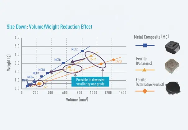
Metal composite inductors come with a remarkably higher energy density compared to their ferrite predecessors. This leads to 30% – 50% smaller case sizes which, for example, serves the trend for downsizing high current ECU power circuits. Furthermore, smaller case sizes also have the pleasant side-effect of being less prone to get damaged in harsh or vibrating environments. A true plus in terms of long term reliability.

See Figure 1. for volume vs weight comparison benchmark between metal composite chip inductors and different types of ferrite inductor types.

Figure 1. Ferrite vs Metal Composite Inductors Volume/Weight comparison; source: Panasonic

DC Bias characteristics

Excellent magnetic saturation characteristics of metal composite inductors (i.e. Ferrite core = 0.4T vs. Metal Composite Type = above 1.5T) render it difficult to magnetically saturate, which in turn is resulting in good inductance vs. current performance, without a substantial drop off. In comparison, ferrite inductors do not only suffer from a fairly quicker inductance drop off.

Their inductance also suffers the undesirable effect that it varies with temperature, whereas the performance of their metal composite counterparts is stable over the entire specified temperature range. Naturally, the qualification of applications using ferrite inductors needs increased effort compared to metal composite inductors due to consideration of different temperature ranges.

Figure 2. Inductance vs DC BIAS current comparison on ferrite and metal composite inductors with temperature; source: Panasonic

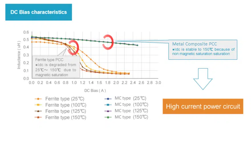
Low loss characteristics of metal composite vs ferrite inductors (see Figure 2.) assist realization of high efficiency power circuits such as ECU and makes thermal design considerations simple.

High Mechanical Shock and Vibration Robustness

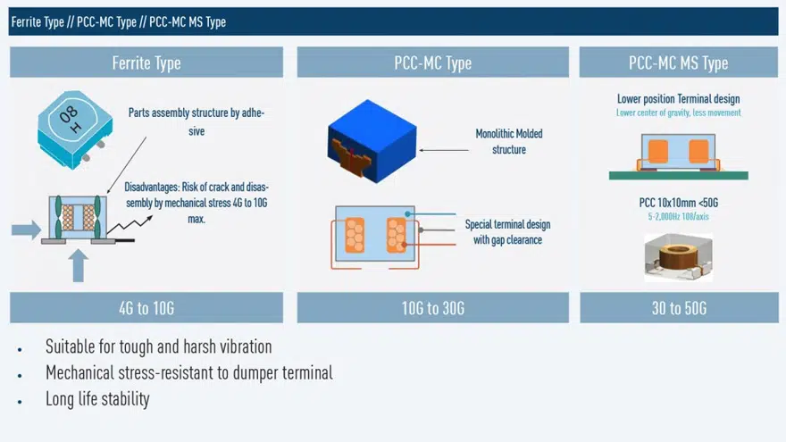
Ferrite inductors consist of several sintered parts being constructively composed with an air gap inside the body, whereas metal composite inductors are based on a monolithic design without air gap.

Due to that assembled structure, the ferrite types’ resistance to vibrations is limited to <4G to maximum 10G. Opposed to that, the monolithic structure of the metal composite inductors leads to a significantly higher vibration resistance – up to 50G, depending on the inductor type – See Figure 3. This may be advantage for harsh environmental, high vibration applications such as automotive, industrial or aerospace/defense electronics.

Figure 3. Mechanical vibration robustness comparison of ferrite vs metal composite (MC) inductors; source: Panasonic

Low EMI noise

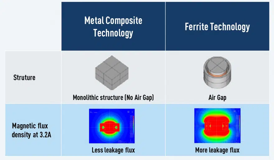
Also in terms of a lower leakage flux outside the power inductors, the point goes to the metal composite types: Their monolithic structure causes by far less leakage as the magnetic flux simply is concentrated inside the inductor housing. See figure 4.

Figure 4. EMI noise / magnetic flux comparison of ferrite vs metal composite inductors; source: Panasonic

Summary

Modern metal composite inductors clearly outperform ferrite technology in many regards and key requirements from modern electronic circuits. Hence, they are more and more finding their way into contemporary application design, in particular in the automotive industry.

Small package sizes, a stable inductance over DC current and temperature, high reliability as well as mechanical robustness and not at least a low EMI noise are nowadays essential prerequisites for next-gen product design. In all these aspects, metal composite inductors make their ferrite ancestors look as old as they are indeed.

Related

Source: Panasonic Industry

Recent Posts

Transformer Design Optimization for Power Electronics Applications

4.11.2025
4

Microhardness — the Hidden Key to Understanding MnOx Cathode Quality in Tantalum Capacitors

3.11.2025
11

Lightweight Model for MLCC Appearance Defect Detection

3.11.2025
9

Bourns Releases High Current Metal Alloy-based, Multilayer Power Chip Inductors

31.10.2025
24

Smiths Interconnect Extends Space-Qualified, High-Reliability Fixed Chip Attenuators 

30.10.2025
10

Samtec Expands Offering of Slim, High-Density HD Array Connectors

30.10.2025
9

Bourns Unveils High-Precision Wirewound Resistor with Long-Term Stability

30.10.2025
21

Common Mode Chokes Selection for RF Circuits in Next-Generation Communication Systems

30.10.2025
14

Capacitor Self-balancing in a Flying-Capacitor Buck Converter

30.10.2025
27

Murata Expands Automotive Metal Frame Y2/X1 Safety MLCC Capacitors to 500V

30.10.2025
32

Upcoming Events

Nov 4
November 4 @ 12:00 - November 6 @ 14:15 EST

Wirebond Materials, Processes, Reliability and Testing

Nov 6
14:30 - 16:00 CET

Self-healing polymer materials for the next generation of high-temperature power capacitors

Nov 11
17:00 - 18:00 CET

Industrial Applications Demand More from Interconnects in Next-Gen Designs

View Calendar

Popular Posts

  • Buck Converter Design and Calculation

    0 shares
    Share 0 Tweet 0
  • Boost Converter Design and Calculation

    0 shares
    Share 0 Tweet 0
  • LLC Resonant Converter Design and Calculation

    0 shares
    Share 0 Tweet 0
  • Flyback Converter Design and Calculation

    0 shares
    Share 0 Tweet 0
  • Ripple Current and its Effects on the Performance of Capacitors

    3 shares
    Share 3 Tweet 0
  • MLCC and Ceramic Capacitors

    0 shares
    Share 0 Tweet 0
  • Dual Active Bridge (DAB) Topology

    0 shares
    Share 0 Tweet 0
  • What is a Dielectric Constant and DF of Plastic Materials?

    4 shares
    Share 4 Tweet 0
  • SEPIC Converter Design and Calculation

    0 shares
    Share 0 Tweet 0
  • Flying Capacitors

    0 shares
    Share 0 Tweet 0

Newsletter Subscription


Passive Components Blog

© EPCI - Leading Passive Components Educational and Information Site

  • Home
  • Privacy Policy
  • EPCI Membership & Advertisement
  • About

No Result
View All Result
  • Home
  • Knowledge Blog
  • PCNS

© EPCI - Leading Passive Components Educational and Information Site

This website uses cookies. By continuing to use this website you are giving consent to cookies being used. Visit our Privacy and Cookie Policy.
Go to mobile version