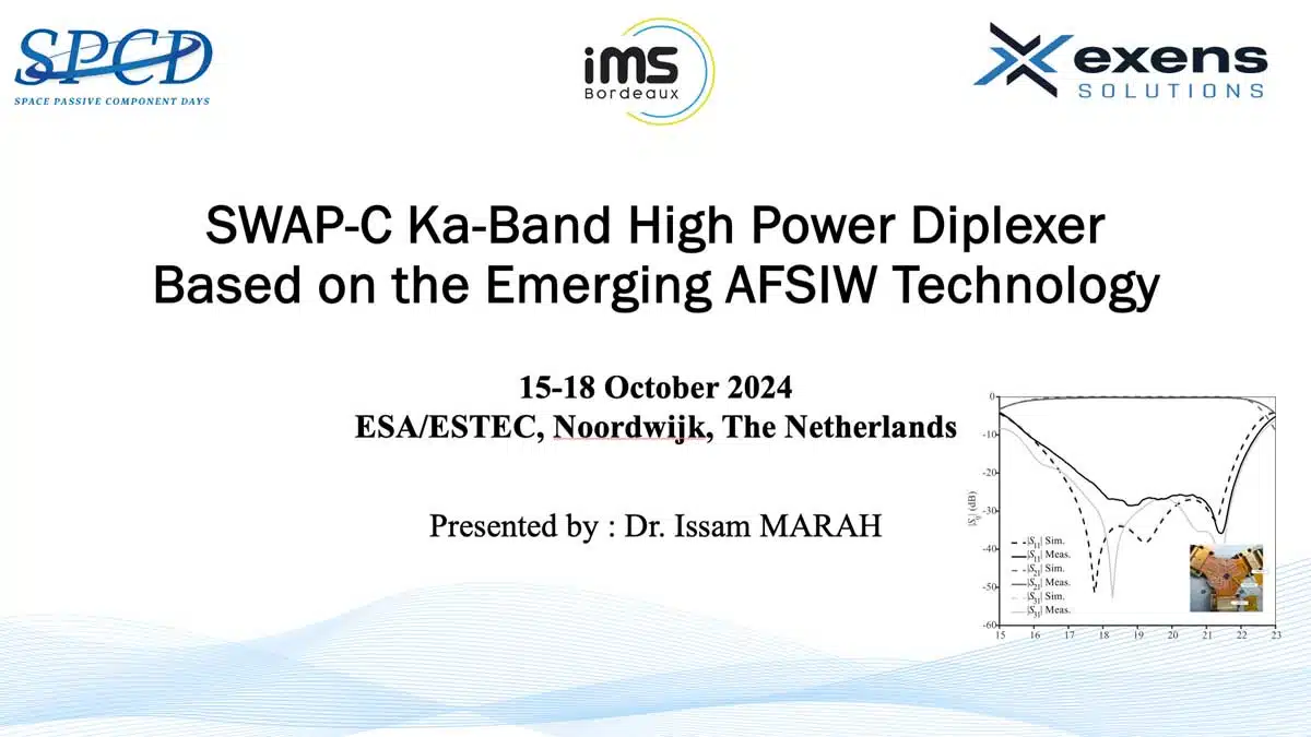
This paper SWAP-C Ka-Band High Power Duplexer Based on the Emerging AFSIW Technology was presented by Issam Marah, Exens-Solutions, France as joined paper with Bordeaux Institute of Technology, France during the 5th Space Passive Component Days (SPCD), an International Symposium held from October 15th to 18th, 2024, at ESA/ESTEC in Noordwijk, the Netherlands. Published under permission from ESA SPCD organizers.
A new vertical waveguide to Air-Filled Substrate Integrated Waveguide AFSIW transition is proposed for duplexer interconnection, offering high power handling and low insertion loss.
The transition, fabricated using three layers of RT/Duroid 6002 substrate, demonstrates insertion losses of less than 0.2 dB and return losses greater than 18 dB in the Ka-band frequency range. The design incorporates a circulator junction with one path coupled to channel 2 of the duplexer, ensuring isolation and independent channel operation.
A broadband AFSIW duplexer is designed using a Y-junction circulator with two asymmetrical gyromagnetic posts. The circulator incorporates ferrite disks for circulation and impedance matching, eliminating the need for metallic ridges. Channel filters, designed using rectangular AFSIW cavities and inductive irises, are integrated with the circulator to achieve duplexer functionality.
An AFSIW duplexer for Ka-band downlink applications was designed, fabricated, and tested. The duplexer, featuring two channel filters coupled through a double junction, demonstrated good thermal stability and met industrial specifications across a temperature range of -20°C to 85°C. The results validate the design model and showcase the potential of AFSIW technology for high-power microwave circuits and systems.
References are cited for research on ferrite-loaded waveguide Y-junctions, partial height ferrite waveguide circulators, and AFSIW termination with absorbing material loading.
Key Points
- Research Topic: Microwave multiplexers for satellite payloads, focusing on size, weight, power, and cost optimization.
- Duplexer Design Goal: Design of an Air-Filled Substrate Integrated Waveguide (AFSIW) duplexer for Ka-band downlink communication, prioritizing SWAP-C savings while adhering to industrial specifications.
- Duplexer Components: The duplexer consists of a waveguide to AFSIW transition, a double-junction (circulator and isolator), and channel filters.
- Duplexer Configuration: The duplexer employs isolated bandpass filters with dual junctions, ensuring independent channel operation and robustness, particularly beneficial for space applications.
- Duplexer Design: The duplexer is designed with circulators to provide isolation between filters, allowing for independent design.
- Waveguide to AFSIW Transition: A new vertical waveguide transition to AFSIW is proposed for interconnecting the duplexer, offering high-power handling and low insertion losses.
- Transition Advantages: The waveguide to AFSIW transition provides advantages such as high-power handling for RF transmission and low insertion losses for RF reception.
- Waveguide to AFSIW Transition Performance: Achieves insertion losses of less than 0.2 dB and return losses greater than 18 dB in the frequency range from 16 GHz to 21.5 GHz.
- Transition Fabrication: Fabricated using three layers of RT/Duroid 6002 substrate with specific thicknesses to match the electric field lines of the horizontal TE10 modes.
- Isolator Design: A Y-junction AFSIW circulator with two asymmetrical gyromagnetic posts is used to ensure independent operation of both channels in the duplexer.
- Isolator Design: Designed a circulator using a magnetized ferrite junction and integrated it with an AFSIW load.
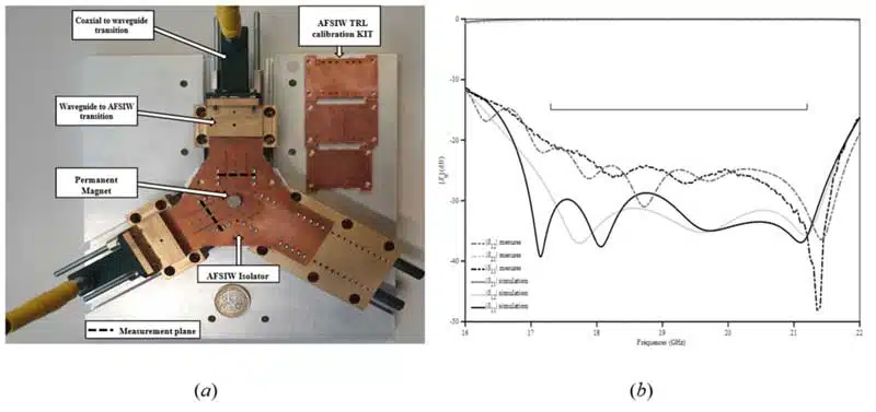
- Performance Evaluation: Evaluated the isolator’s performance using a test fixture and AFSIW TRL calibration kit, achieving return loss, isolation, and insertion loss better than 21 dB, 22 dB, and 0.3 dB, respectively.
- Simulation and Measurement Agreement: Achieved good agreement between simulated and experimental small-signal results.
- Channel Filter Design: Two channel filters were designed using rectangular AFSIW cavities coupled via inductive irises, achieving a fourth-order filter topology with four cavities and five coupling irises.
- Duplexer Design: The channel filters were integrated with circulators to achieve the duplexer function, allowing for independent operation of each filter.
- Duplexer Measurement: A demonstration duplexer was designed, fabricated, and measured to evaluate its electrical performance and validate the design model.
- Duplexer Fabrication: Fabricated using three layers of RT/Duroid 6002 substrate, with the middle layer (S2) playing an electromagnetic role and the other two layers providing mechanical support.
- Duplexer Components: Components include ferrites, absorbers, WR51 flanges, samarium magnets, mild steel yokes, and tuning screws for performance compensation.
- Duplexer Performance Evaluation: Evaluated using a vector network analyzer and TRL WR51 calibration kit, with simulation and measurement results showing good agreement.
- Thermal Stability: The AFSIW duplexer demonstrates good thermal stability with a maximum variation of -20 ppm across the temperature range of -20 °C to 85 °C.
- Performance Parameters: The duplexer meets the required specifications for matching, insertion loss, and isolation across the frequency range of 17.37-22 GHz.
- Duplexer Design: A Ka-band duplexer design for downlink applications, featuring a double junction with a circulator and an isolator, interconnected with waveguides and AFSIW lines.
- Waveguide-to-AFSIW Transition: Successful realization of a low-loss (maximum 0.2 dB) and wide-bandwidth (25%) transition from waveguide to AFSIW, using integrated impedance transformers.
- Duplexer Performance: Demonstrated functionality and low insertion loss across a temperature range of -20 to 85 °C, showcasing potential for high-power microwave circuits and systems.
Introduction
Microwave multiplexers are essential for separating or combining different frequency bands in satellite communications. Various configurations of input multiplexers (IMUX) are employed, particularly in multi-beam payloads. Signals received by the IMUX are routed to high-power amplifiers (HPAs) after undergoing frequency conversions.
Multiplexers make SWAP-C critical design factors for these components. This paper presents the design of an Air-Filled Substrate Integrated Waveguide (AFSIW) duplexer for downlink communication in the Ka-band. It adheres to industrial specifications and aims for SWAP-C savings.
The duplexer is designed with two coupled channel filters via a double-junction of a circulator and an isolator.
For duplexer interconnection, a waveguide to AFSIW transition is explored. It’s designed based on impedance transformers integrated into the waveguide and multilayer Printed Circuit Board (PCB) of the AFSIW line. Low insertion loss and wide bandwidth operation are achieved. Tuning screws are integrated to compensate for manufacturing tolerances and improve production yield.
The core element, a double-junction (circulator and isolator), is designed with a wideband circulator and a load. Mild steel brackets optimize polarization and ensure a magnetostatic seal. The isolator is fabricated and tested under weak signal conditions.
Channel filters are synthesized and integrated with other components. The AFSIW duplexer is fabricated, assembled, and measured under low signal conditions.
Duplexer Building Blocs Description
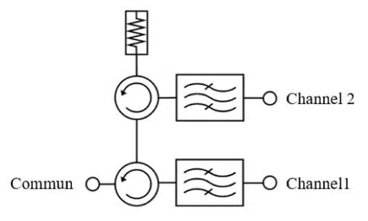
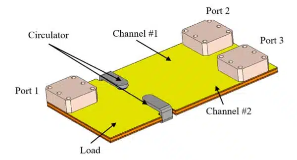
The configuration illustrated in Figure 1 uses isolated bandpass filters with dual junctions that include circulators and isolators. This design ensures independent channel operation, making it robust in space applications. Variations in one channel’s impedance don’t impact others.
The circulators provide effective isolation between filters, enabling independent design.
Several transitions have been proposed for interconnecting AFSIW equipment, focusing on coplanar or microstrip lines. However, coplanar lines have limitations: increased noise figure in reception mode due to insertion losses and power handling issues.
Waveguide to AFSIW Interconnexion
A waveguide to AFSIW transition offers high-power handling for RF transmission and low insertion losses for RF reception. The first horizontal waveguide transition to AFSIW was presented in 2017. It’s based on the same principle as the waveguide transition to AFSIW presented in [5]. Figure 2 illustrates it. It uses sections of waveguide of different heights for progressive impedance matching, providing impedance matching over a 30% bandwidth in the Ka band with low insertion and return loss. Tested in vacuum, its power handling exceeds 200 W. However, its horizontal aspect limits its use in embedded systems. It’s only been used for measuring AFSIW circuits in both high and low signal conditions.
A new vertical waveguide transition to AFSIW is proposed (Figure 3). It consists of two identical WR51 flanges coupled to the AFSIW line through an opening in the substrate S1. Substrates S1 and S2 are used for impedance matching between the vertical waveguide and the horizontal AFSIW line.
Impedance matching in the waveguide to AFSIW transition involves matching the electric field lines of the horizontal TE10 modes. The proposed waveguide was fabricated using three layers of RT/Duroid 6002 substrate. Substrate S2 has a thickness of 1.524 mm, while substrates S1 and S3 have a thickness of 0.508 mm. A standard Thru, reflect, and line (TRL) waveguide WR51 calibration kit was used to eliminate cable and transition effects, allowing for in-plane measurement. Simulations and measurements demonstrate the transition’s performance, with insertion losses less than 0.2 dB and return losses greater than 18 dB from 16 GHz to 21.5 GHz.
Isolator Design
The isolator design for the duplexer involves a circulator junction coupled to channel 2 and terminated with a matched load. To ensure independent operation of both channels across the duplexer’s frequency bands, a broadband design is required.
A Y-junction AFSIW circulator with two asymmetrical gyromagnetic posts is presented. The topology is illustrated in Figure 2(b). It features two ferrite disks, ferrite 1 and ferrite 2, positioned at the bottom and top centers of the waveguide Y-junction, respectively. The ferrites differ in diameter (Df1 and Df2) and height (Hf1 and Hf2). The larger ferrite disk at the bottom is positioned at the bottom center of the waveguide Y-junction.
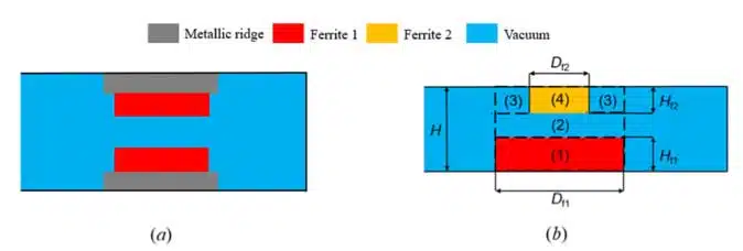
The larger ferrite disk at the bottom is responsible for establishing the circulation conditions, while the smaller ferrite disk at the top improve the impedance matching between the ferrite loaded junction and three waveguide arms. The patented circulator topology from Exens-Solutions is a pioneering design, utilizing ferrite not only for its non-reciprocal properties but also for impedance matching. This approach enhances the utility of ferrite, reducing the reliance on conventional ridge transformers typically used in commercial circulators shown in Figure 2(a). Consequently, this topology presents a strong candidate for AFSIW technology, eliminating the need for ridges, which are costly to fabricate with PCB.
The ferrite 1 disk achieves the circulation. It acts as a magnetized planar resonator involving a pair of rotational hybrid modes: the clockwise HE+11 mode and the anti-clockwise HE-11 mode. The ferrite 2 disk provides an additional degree of freedom allowing impedance matching. It has influence on the in-phase TM01 mode without significantly impacting the rotational modes. In this purpose, the ferrite 2 disk is smaller in diameter than the ferrite 1 disk. The dimensioning of the planar ferrite resonator (ferrite 1) depends only on the in-phase TM01 mode when considering a demagnetized junction, hence the effective permittivity of the junction. In the proposed structure, the junction consists of regions {1} to {4} shown in Figure 2(b). Here, identical ferrite materials are considered for both disks.
The proposed AFSIW isolator is designed to achieve a return loss and isolation better than 25 dB across the 17.3 to 21.2 GHz frequency range. The design involves using lithium ferrite to facilitate impedance matching between the junction and the AFSIW waveguide arms. The circulator is integrated with an AFSIW load, and the isolator is fabricated using multilayer technology. The performance is evaluated using a test fixture designed for measuring AFSIW components, and an AFSIW TRL calibration kit is used to de-embed cables and interconnection effects. The simulated and experimental small-signal results show a very good agreement. The proposed AFSIW isolator achieves a return loss, isolation, and insertion loss better than 21 dB, 22 dB, and 0.3 dB, respectively.
Chanel Filter Design
After validating the basic components, the thesis reported bandpass filter implementations for the same frequency band. Based on these works, the two channel filters are designed using rectangular AFSIW cavities coupled via inductive irises. To meet rejection specifications, the proposed topology is a fourth-order filter with four cavities and five coupling irises. The filters were designed using FEST 3D software.
The channel filters were integrated with the basic components to achieve the duplexer function. Each channel is coupled by a circulator, allowing independent operation and simplifying the design.
Duplexer Design
For demonstration, the AFSIW duplexer was designed, fabricated, and measured to evaluate its electrical performance and validate the design model.
The duplexer, fabricated with three layers of RT/Duroid 6002 substrate, has a thickness of Hs2 = 1.52mm. Substrates S1 and S3 provide mechanical support but influence the distance between magnets and ferrites, as well as power dissipation.
Ferrites, absorbers, and WR51 flanges were cut and bonded with low-thickness, low-EM-loss epoxy adhesive. For saturated ferrite polarization, two samarium magnets with a remanent magnetic field of 0.92 T were glued to substrates S1 and S3. Mild steel yokes ensured proper operation and magnetostatic sealing.
Tuning screws were introduced in the waveguide-to-AFSIW transition, cavities, and irises of each channel filter to compensate for manufacturing tolerances. Vector network analyzers and a TRL WR51 calibration kit eliminated transition and cable effects. Simulation and measurement results, shown in Figures 12 and 13, showed good agreement.
Environmental measurements were conducted to evaluate the duplexer’s performance.
Temperatures range from -20 °C to 85 °C. Figure 14 shows the duplexer channels’ transmission and matching at these temperatures. The AFSIW duplexer has good thermal stability, maintaining -20 ppm. Tables 2 and 3 summarize the measurements, confirming the duplexer’s proper functioning and compliance with specifications.
Conclusion
This work presents the design of an AFSIW duplexer for Ka band downlink applications, meeting industrial specifications. It consists of two channel filters coupled through a double junction (circulator and isolator).
To connect the duplexer to waveguides, impedance transformers were integrated into the waveguide and AFSIW line. The waveguide-to-AFSIW transition was successfully realized and measured, achieving low insertion losses (maximum 0.2 dB) and a wide bandwidth (25%).
The central element, a double junction, was designed with a broadband circulator and a load. The isolator was fabricated and measured under low signal conditions.
Fourth-order AFSIW channel filters were synthesized and integrated to meet the required specifications. The duplexer was fabricated, assembled, and measured under low signal conditions across a temperature range of -20 to 85 °C.
This development extends PCB capabilities and opens the door for substrate integration of high-power microwave circuits and systems envisioned by the authors for the industry, particularly for new space applications.
Read the full paper: