








Passive Components Blog
No Result
View All Result
  • Home
  • NewsFilter
    • All
    • Aerospace & Defence
    • Antenna
    • Applications
    • Automotive
    • Capacitors
    • Circuit Protection Devices
    • electro-mechanical news
    • Filters
    • Fuses
    • Inductors
    • Industrial
    • Integrated Passives
    • inter-connect news
    • Market & Supply Chain
    • Market Insights
    • Medical
    • Modelling and Simulation
    • New Materials & Supply
    • New Technologies
    • Non-linear Passives
    • Oscillators
    • Passive Sensors News
    • Resistors
    • RF & Microwave
    • Telecommunication
    • Weekly Digest

    Planar vs Conventional Transformer: When it Make Sense

    Researchers Propose Next‑Gen Compact Memory Using Ultra-thin Ferroelectric Capacitors

    Nichicon ADN Automotive Hybrid Aluminum Capacitors Now Available in EMEA

    Wk 19 Electronics Supply Chain Digest

    Electrocaloric Multilayer Capacitors: Towards Quiet, Solid‑State Cooling Around Room Temperature

    High-Crystallinity Nanocrystalline Composites for MHz Chip Inductors

    European Components Distribution Shows Strong Q1 2026 Growth Amid Geopolitical Uncertainty

    Stackpole Expanded its AlN Thick Film Chip Resistors

    KYOCERA 10 µF 0201 MLCC Brings High‑Capacitance into Mobile Designs

    Trending Tags

    • Ripple Current
    • RF
    • Leakage Current
    • Tantalum vs Ceramic
    • Snubber
    • Low ESR
    • Feedthrough
    • Derating
    • Dielectric Constant
    • New Products
    • Market Reports
  • VideoFilter
    • All
    • Antenna videos
    • Capacitor videos
    • Circuit Protection Video
    • Filter videos
    • Fuse videos
    • Inductor videos
    • Inter-Connect Video
    • Non-linear passives videos
    • Oscillator videos
    • Passive sensors videos
    • Resistor videos

    Planar vs Conventional Transformer: When it Make Sense

    Modeling Fringing Field Losses in Inductors & Transformers

    Why Power Inductors Use a Ferrite Core With an Air Gap

    Transformer-Based Power-Line Harvester Magnetic Design

    Thermal Modeling of Magnetics

    Standard vs Planar LLC transformers Comparison for Battery Chargers

    How Modern Tools Model Magnetic Components for Power Electronics

    Advanced Loss Modeling for Planar Magnetics in the Frenetic Planar Tool

    2026 Power Magnetics Design Trends: Flyback, DAB and Planar

    Trending Tags

    • Capacitors explained
    • Inductors explained
    • Resistors explained
    • Filters explained
    • Application Video Guidelines
    • EMC
    • New Products
    • Ripple Current
    • Simulation
    • Tantalum vs Ceramic
  • Knowledge Blog
  • DossiersNew
  • Suppliers
    • Who is Who
  • PCNS
    • PCNS 2025
    • PCNS 2023
    • PCNS 2021
    • PCNS 2019
    • PCNS 2017
  • Events
  • Home
  • NewsFilter
    • All
    • Aerospace & Defence
    • Antenna
    • Applications
    • Automotive
    • Capacitors
    • Circuit Protection Devices
    • electro-mechanical news
    • Filters
    • Fuses
    • Inductors
    • Industrial
    • Integrated Passives
    • inter-connect news
    • Market & Supply Chain
    • Market Insights
    • Medical
    • Modelling and Simulation
    • New Materials & Supply
    • New Technologies
    • Non-linear Passives
    • Oscillators
    • Passive Sensors News
    • Resistors
    • RF & Microwave
    • Telecommunication
    • Weekly Digest

    Planar vs Conventional Transformer: When it Make Sense

    Researchers Propose Next‑Gen Compact Memory Using Ultra-thin Ferroelectric Capacitors

    Nichicon ADN Automotive Hybrid Aluminum Capacitors Now Available in EMEA

    Wk 19 Electronics Supply Chain Digest

    Electrocaloric Multilayer Capacitors: Towards Quiet, Solid‑State Cooling Around Room Temperature

    High-Crystallinity Nanocrystalline Composites for MHz Chip Inductors

    European Components Distribution Shows Strong Q1 2026 Growth Amid Geopolitical Uncertainty

    Stackpole Expanded its AlN Thick Film Chip Resistors

    KYOCERA 10 µF 0201 MLCC Brings High‑Capacitance into Mobile Designs

    Trending Tags

    • Ripple Current
    • RF
    • Leakage Current
    • Tantalum vs Ceramic
    • Snubber
    • Low ESR
    • Feedthrough
    • Derating
    • Dielectric Constant
    • New Products
    • Market Reports
  • VideoFilter
    • All
    • Antenna videos
    • Capacitor videos
    • Circuit Protection Video
    • Filter videos
    • Fuse videos
    • Inductor videos
    • Inter-Connect Video
    • Non-linear passives videos
    • Oscillator videos
    • Passive sensors videos
    • Resistor videos

    Planar vs Conventional Transformer: When it Make Sense

    Modeling Fringing Field Losses in Inductors & Transformers

    Why Power Inductors Use a Ferrite Core With an Air Gap

    Transformer-Based Power-Line Harvester Magnetic Design

    Thermal Modeling of Magnetics

    Standard vs Planar LLC transformers Comparison for Battery Chargers

    How Modern Tools Model Magnetic Components for Power Electronics

    Advanced Loss Modeling for Planar Magnetics in the Frenetic Planar Tool

    2026 Power Magnetics Design Trends: Flyback, DAB and Planar

    Trending Tags

    • Capacitors explained
    • Inductors explained
    • Resistors explained
    • Filters explained
    • Application Video Guidelines
    • EMC
    • New Products
    • Ripple Current
    • Simulation
    • Tantalum vs Ceramic
  • Knowledge Blog
  • DossiersNew
  • Suppliers
    • Who is Who
  • PCNS
    • PCNS 2025
    • PCNS 2023
    • PCNS 2021
    • PCNS 2019
    • PCNS 2017
  • Events
No Result
View All Result
Passive Components Blog
No Result
View All Result

Vishay Releases X1, X2, and Y2 EMI Suppression Film Capacitors Certified to IEC 60384-14

27.8.2019
Reading Time: 2 mins read
A A

Source: Vishay news

MALVERN, Pa. Vishay Intertechnology, Inc. today introduced three new series of X1, X2, and Y2 electromagnetic interference (EMI) suppression film capacitors for standard across the line and line bypass applications.

RelatedPosts

Planar vs Conventional Transformer: When it Make Sense

Researchers Propose Next‑Gen Compact Memory Using Ultra-thin Ferroelectric Capacitors

Nichicon ADN Automotive Hybrid Aluminum Capacitors Now Available in EMEA

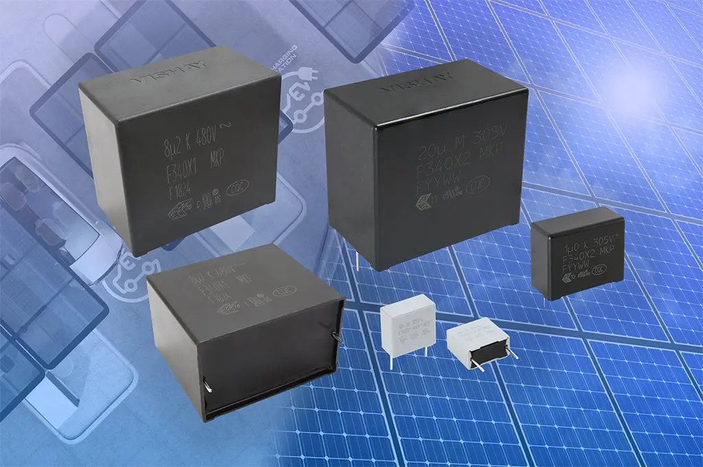
Designed to meet the most stringent requirements for robustness against humidity, the new F340 EMI suppression family is certified to IEC 60384-14: 2013 ed. 4 / AMD1: 2016 grade IIIB: “High Robustness Under High Humidity.”

To comply with the humidity grading system defined under IEC 60384-14: 2013 ed. 4 / AMD1: 2016 grade IIIB, the Vishay BCcomponents devices released today withstand temperature humidity bias (THB) testing of 85 °C, 85 % relative humidity for 1000 hours while biased at the rated AC voltage with high stability on capacitance, dissipation factor, and insulation resistance. This translates into longer service life under harsh application conditions for industrial and automotive power electronics, such as battery chargers, renewable energy inverters, motor drives, and UPS.

The F340X1 is designed for a rated voltage of 480 VAC. It offers a broad capacitance range from 0.22 µF to 8.2 µF, while withstanding operation voltages up to 530 VAC to ensure compliance with permissible voltage variations on three-phase mains. The F340X2 has a rated voltage of 305 VAC and provides a capacitance range from 1 µF to 20 µF, with  high ripple current capabilities up to 18 A at 10 kHz. Also featuring a rated voltage of 305 VAC, the F340Y2 is qualified in accordance with AEC-Q200, Automotive Grade and provides a capacitance range from 0.01 µF to 1 µF.

The entire F340 family is certified in accordance with EN, UL and CQC for Safety and Humidity Robustness. The capacitors offer lead pitches of 15 mm, 22.5 mm, 27.5 mm, 37.5 mm and 52.5 mm. Their encapsulation consists of a flame-retardant UL-class 94 V-0 plastic case and epoxy resin sealing. All three series are lead (Pb)-free and RoHS-compliant; F340X1 480VAC and F340X2 305VAC devices are also halogen-free and Vishay Green.

Device Specification Table:

Series F340X1 480VAC F340X2 305VAC F340Y2 305VAC
Capacitance 0.22 μF to 8.2 μF 1 μF to 20 μF 0.01 μF to 1 μF
Tolerance ± 10 %; ± 20 % ± 10 %; ± 20 % ± 5 %; ± 10 %; ± 20 %
Permissible DC voltage 800 VDC at 105 °C 630 VDC at 105 °C 1000 VDC at 105 °C
THB 85 °C, 85 % RH for 1000 hours at URAC

Samples of the new X1, X2, and Y2 capacitors are available now, with lead times of 16 weeks.

Related

Recent Posts

Planar vs Conventional Transformer: When it Make Sense

11.5.2026
4

Researchers Propose Next‑Gen Compact Memory Using Ultra-thin Ferroelectric Capacitors

11.5.2026
6

Nichicon ADN Automotive Hybrid Aluminum Capacitors Now Available in EMEA

11.5.2026
9

Electrocaloric Multilayer Capacitors: Towards Quiet, Solid‑State Cooling Around Room Temperature

7.5.2026
138

Stackpole Expanded its AlN Thick Film Chip Resistors

6.5.2026
20

KYOCERA 10 µF 0201 MLCC Brings High‑Capacitance into Mobile Designs

6.5.2026
45

Würth Elektronik Introduces Compact Flat-wire SMT Power Inductors for Automotive

5.5.2026
44

KYOCERA AVX Extends MLV Varistors for 48V Automotive Protection

5.5.2026
21

Energy Localization in Tantalum Anode Formation: A Structural Perspective

4.5.2026
41

Upcoming Events

May 12
8:00 - 15:00 CEST

ESCC Space Splice connectors

May 12
16:00 - 17:00 CEST

Accelerating Power Supply Design with Wurth Elektronik and STMicroelectronics

May 13
17:00 - 17:30 CEST

Winding Loss Modeling for Toroidal Magnetics – Including Gapped Cores

View Calendar

Popular Posts

  • Buck Converter Design and Calculation

    0 shares
    Share 0 Tweet 0
  • Boost Converter Design and Calculation

    0 shares
    Share 0 Tweet 0
  • Flyback Converter Design and Calculation

    0 shares
    Share 0 Tweet 0
  • LLC Resonant Converter Design and Calculation

    0 shares
    Share 0 Tweet 0
  • MLCC and Ceramic Capacitors

    0 shares
    Share 0 Tweet 0
  • Dual Active Bridge (DAB) Topology

    0 shares
    Share 0 Tweet 0
  • Capacitor Charging and Discharging

    0 shares
    Share 0 Tweet 0
  • What Electronics Engineer Needs to Know About Passive Low Pass Filters

    0 shares
    Share 0 Tweet 0
  • Ripple Current and its Effects on the Performance of Capacitors

    3 shares
    Share 3 Tweet 0
  • MLCC Case Sizes Standards Explained

    0 shares
    Share 0 Tweet 0

Newsletter Subscription


Passive Components Blog

© EPCI - Leading Passive Components Educational and Information Site

  • Home
  • Privacy Policy
  • EPCI Membership & Advertisement
  • About

No Result
View All Result
  • Home
  • Knowledge Blog
  • PCNS

© EPCI - Leading Passive Components Educational and Information Site

This website uses cookies. By continuing to use this website you are giving consent to cookies being used. Visit our Privacy and Cookie Policy.
Go to mobile version