source: Microwave & RF news
Feb 10, 2016 Jack Browne | Microwaves and RF
Components based on SAW and BAW technology both employ acoustic waves but in different ways and with different performance levels, especially at higher frequencies.
Acoustic waves may seem out of the useful range of RF/microwave designs, but such low-frequency waves are quite effective in higher-frequency systems. They form the foundation for surface-acoustic-wave (SAW) and bulk-acoustic-wave (BAW) resonators, filters, oscillators, and delay lines. Components based on these technologies have found their ways into many applications, from automotive navigation systems and smartphones to military radar systems.
SAW and BAW components provide special characteristics that cannot be found in purely electronic components, with high performance levels. But how do they differ? What conditions favor a SAW filter over a BAW filter, or vice versa?
Both SAW and BAW components employ interdigital transducers (IDTs) to convert electrical energy to mechanical acoustic waves and then back to electrical energy, enabling signal processing in the acoustic realm. Given how RF/microwave frequencies can be translated into shorter-wavelength acoustic signals, it’s possible to create extremely small filters and resonators for SAW structures that process higher-frequency electromagnetic (EM) signals.
These small structural features, however, ultimately limit the high-end frequency for which a SAW filter or resonator can be practically manufactured. Power-handling capabilities also become limited due to the high current densities in small structures.
Different But Complementary
In a SAW component, acoustic waves travel across the surface of an elastic, piezoelectric material, with wave amplitude that typically decays exponentially with depth into the substrate material.
This acoustic-wave phenomenon was first discovered in 1885 by Lord Rayleigh, who used it to explain how acoustic waves travel along the surface of the earth following an earthquake. For that reason, the acoustic waves across a SAW filter are sometimes referred to as Rayleigh waves. In contrast, the acoustic waves in a BAW component travel through and are stored in the piezoelectric material.
If anything, SAW and BAW are complementary technologies. SAW components such as filters can be manufactured to about 2.0 or 2.5 GHz before the dimensions of the SAW transducers become unmanageably small. BAW components, on the other hand, are sometimes known as “high-frequency SAWs” and can be used to 2.7 GHz and beyond for filtering, delay lines, and other functions. For some applications, such as Long Term Evolution (LTE) wireless systems, SAW and BAW filters both play roles; in this case, at the lower- and higher-frequency bands, respectively.
")
Since SAW filters are known to drift in frequency more with temperature than BAW filters, some designers opt for BAW filters in circuits or systems that must be used over wide operating-temperature ranges. In recent years, though, a number of SAW manufacturers have developed either temperature-compensated or more temperature-insensitive SAW filters that provide stable frequency operation even over wide operating-temperature ranges.
Piezo is Primary Material
SAW and BAW components rely on piezoelectric materials to transfer or store acoustic energy, and the choice of material can have a great impact on filter or resonator performance. In either type of component, the piezoelectric material layer is usually produced with top and bottom metal layers and mounted to a substrate material for stability. Piezoelectric materials for SAW components must exhibit optimum mechanical and electrical properties.
Movement of the surface waves can vary with the type of substrate material, such as lithium niobate (LiNbO3) or lithium tantalite (LiTaO3). One piezoelectric material that has gained widespread acceptance for its manufacturability and performance levels is aluminum nitride (AlN). In addition to SAW and BAW devices, piezoelectric materials are also used in the fabrication of microelectromechanical-systems (MEMS) components.
Piezoelectric material can also support different bandwidths for SAW filters, depending on the type. Basic quartz materials have been found to be adequate for low-bandwidth filters, while lithium tantalite has served well for medium-bandwidth varieties. Lithium niobate is typically employed for SAW filters with wide bandwidths. As with most high-frequency components, however, these materials yield other tradeoffs in exchange for such performance characteristics. In particular, lithium niobate is known for high temperature dependency and higher loss than some of the other piezoelectric materials.
To form a SAW or BAW filter or resonator, different types of metal films are deposited on the top and bottom of the piezoelectric materials. These metals include aluminum (Al) and tungsten (W), for lower and higher power levels, respectively. In such acoustic components, the resonant frequency is inverse proportional to film thickness, with both the metal and dielectric layers helping to determine the resonant frequency. Removing some of the top layer metal thickness, for example, can increase the resonant frequency.
Storing acoustic-wave energy within the piezoelectric material has its advantages. At their higher frequencies, BAW resonators are capable of achieving high quality factors (Qs) that translate into highly selective filters. For bandpass filters, for example, low passband insertion loss is possible with very sharp filter skirts. This enables high rejection of signals closely located to a desired passband, as has become the case for many of the wireless communications standards. BAW filters tend to be better suited for higher-power-level signals than SAW filters with their fine circuit features that can suffer the performance-degrading effects of electromigration at higher power levels.
As delay lines, both technologies are effective within their frequency ranges, with SAW delay lines somewhat smaller in size and less expensive than BAW delay lines. SAW delay lines operate at lower frequencies than BAW delay lines, and are somewhat limited in terms of the amount of delay time that they can introduce to a circuit or system compared to their BAW counterparts.
What’s Available?
As frequency resonators or oscillators, SAWs have demonstrated extremely low-noise performance, with outstanding phase noise. Synergy Microwave Corp., for example, known for its crystal oscillators and phase-locked oscillators, also supplies a line of SAW oscillators through about 2 GHz. The firm’s HFSO800-5H voltage-controlled SAW oscillator provides a stable output at 800 MHz when running on 20 mA from +0.5 to +5.0 V dc. It exhibits extremely low single-sideband (SSB) phase noise of –150 dBc/Hz offset only 10 kHz from the carrier. The oscillator, and other members in the SAW oscillator line, comes in a compact surface-mount-device (SMD) package.
For higher frequencies, the model VS-401 voltage-controlled SAW oscillator from Vectron International is available from 1.3 to 2.5 GHz for optical receivers and data converters. For a frequency of 1.75 GHz, SSB phase noise is –119 dBc/Hz offset 10 kHz from the carrier. It is supplied in a 13- × 20-mm SMD package, although the firm offers SAW filters and oscillators in surface-mount, through-hole, and connector-equipped packages.
")
One unmistakable trend is toward the design and production of both smaller SAW and BAW components to reduce a circuit’s footprint and weight as much as possible. As electronic end products continue to be made smaller, lighter, and more portable, component designers feel greater pressure to develop correspondingly smaller and lighter signal-processing components, such as filters. Qorvo’s recent unveiling of SAW and BAW filters proves this point.
In another example, Qorvo and RFMW Ltd. announced the availability of the model 885128 BAW filter from TriQuint for 2.4-GHz coexistence of multiple wireless standards, notably WLAN, Wi-Fi, and Bluetooth systems. The BAW filter allows the wireless technologies to coexist in the presence of Fourth Generation (4G) Long Term Evolution (LTE) wireless communications systems.
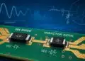
The 885128 employs the firm’s LowDrift and NoDrift temperature-stabilization technologies to minimize frequency drift with temperature over an operating-temperature range of –40 to +95°C. It handles as much as 4 W (+36 dBm) input power in a SMD housing measuring just 1.1 × 0.9 × 0.5 mm (Fig. 1).
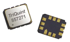
At the same time, Qorvo and RFMW introduced the higher-frequency model 857271 456-MHz SAW filter. It provides a 39.6-MHz, 1.4-dB bandwidth at a center frequency of 456 MHz for use with WCDMA/LTE applications. It is housed in a ceramic surface-mount package measuring 7.01 × 5.51 × 1.70 mm (Fig. 2).
As a simple “difference between” for SAW and BAW components, BAW devices can handle higher frequencies and higher power levels than SAW components, although SAW components tend to be less costly. Of course, with the Qorvo example, both filter types were housed in similar-appearing SMD packages, albeit with a significant difference in the center frequencies of the filters. In general, these technologies are different but quite complementary, and it is not unusual to have components from both types of technologies within the same system design.