


Don’t risk design catastrophe. Choosing such a critical component demands intensive research on specs and capabilities of all similar device types.
Overload prevention in any given design is serious business, which means that the choice of Safety capacitors (see quick guide here) shouldn’t be taken lightly either. Areas to consider in the decision process include safety requirements, type of filtering, the pros and cons of different device types, the consequences of device failure, and much more. This article provides a quick reference to the most important of these factors when selecting a device.
1. The class of capacitor you need depends on whether you’re doing differential-mode or common-mode filtering.
- Differential-mode interference is when pulses run along the wires (L-N) in opposite directions. For differential-mode filtering, you need Class X capacitors connected between the lines, effectively returning high-frequency interference back to its source.
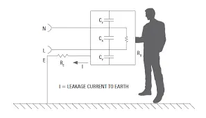
- Common-mode interference is when pulses run in the same direction in both wires (L-N) in the same device. For common-mode filtering, you need Class Y capacitors connected between the wires and ground, bypassing the interference pulses from the wires to the ground.

The full-range, ac-filtering film capacitors shown here (MKP1847H) can withstand demanding temperature-humidity-bias (THB) testing—85°C, 85% RH for 1,000 hours at rated voltage—without altering their electrical characteristics. The capacitors feature segmented film, a rated capacitance from 1 to 35 µF, and ESR down to 3 mΩ. The devices provide ripple current capabilities up to 24.5 A and rated voltages of 250, 310, 350, and 480 V ac.
2. Safety requirements differ depending on the type of capacitor.
- The noise level in all electronic/electric devices has to be kept below a certain level, which is defined in the standard for the particular device.
- Filtering is done by components such as capacitors or chokes, or a combination of these components.
- Since safety capacitors operate directly connected to the mains, they have to meet the requirements of the IEC 60384-14 safety standard.
- The safety requirements are much higher for Y capacitors, because a short/failure of such a component could present an immediate danger of an electric shock (see below).
3. While capacitor shorts in Class X1/X2/X3/X4 applications aren’t a big deal, they can lead to electrocution in Class Y1/Y2/Y3 applications due to higher surge levels.
- Failure of an X or a Y capacitor will lead to the malfunction or destruction of the device.
- A crack in a surface-mount part, built by putting two capacitors in series, can result in diminished capacitance rather than a short, since a short may occur in one section without affecting the other.
- Since X capacitors connect line and neutral, failure would not lead to the danger of an electric shock. However, it could open safety fuses or circuit breakers, and in an extreme case, catch on fire.
- Y capacitors are located between a live conductor and the metal shielding, which someone could touch, so their failure can cause electric shocks.
4. There are pros and cons to using film capacitors.
The pros:
- Film capacitors offer higher capacitance values compared to other technologies. Take, for example, Vishay’s film capacitors and their ratings (see table).
- Film capacitors have the ability to recover from a dielectric breakdown with just a tiny decrease in capacitance. This is called a “self-healing” effect. It happens because the arc created during a dielectric breakdown evaporates the metallization layer and thus clears the fault condition.
- The capacitance and dissipation factor of film capacitors are highly stable across a wide temperature range from −40 to +110°C.
- The internal series construction of X2 film safety capacitors helps the device last longer and maintain capacitance in series impedance or across-the-line applications.

The cons:
- Film safety capacitors are through-hole devices, and if the application uses surface-mount components, they may need a different soldering process than the other components on the board.
- Film capacitors are usually more expensive than ceramic capacitors.
5. Ceramic capacitors also have their pros and cons.
The pros:
- Leaded ceramic capacitors have the highest dielectric and pulse strength of all technologies.
- Leaded ceramic capacitors are the only ones available in the X1/Y1 safety classification.
- Leaded ceramic capacitors can handle pulses up to 10 kV.
- Surface-mount ceramic capacitors are available with a capacitance value of 1 nF and an NP0 temperature coefficient of capacitance.
- Leaded ceramic capacitors are usually less expensive than film capacitors.
The cons:
- Ceramic capacitors have relatively low capacitance values compared to other technologies, so they can’t be used in some applications.

These surface-mount multilayer ceramic chip capacitors (MLCCs) (VJ safety certified capacitors) come with C0G (NP0) and X7R dielectrics, each offering X1/Y2 and X2 safety classifications with 250-V ac voltage ratings. They’re optimized for EMI and ac-line filtering, and lightning-strike and voltage-surge protection in power supplies, battery chargers, and isolators for telecom systems, ac equipment, and appliances.
6. How you arrange components on the board has an effect on whether you’re meeting safety requirements.
- The market is always driving toward smaller components, but compliance with IEC 60384-14 means safety capacitors need to follow guidelines for creepage and clearance distances.
- For X1/Y1 capacitors, the minimum allowed creepage and clearance distance is 8 mm.
- Surface-mount capacitors also need to meet certain standards for termination-to-termination creepage.
- Look for surface-mount capacitors that meet the strict 4-mm test.
7. Surface-mount capacitors have a lower total implementation cost than through-hole capacitors.
- Through-hole devices may be less per piece, but they cost more to assemble.
- As a rough estimate, it costs less than $0.01 to assemble an surface-mount part versus $0.05 to assemble a through-hole part.
8. Not all single-layer capacitors are equal, regardless of what their datasheets may say. Examples include:
- Although it’s sufficient for a X1/Y1 capacitor to withstand 8-kV pulses according to IEC 60384-14, components are available with pulse strengths of 10 kV.
- Devices qualified with a biased 85/85 1000-hour test are available, even though this isn’t required by the IEC standard (which requires only 40/95 500 hours).
- Capacitors using silver electrodes instead of copper provide improved component lifespan, since they eliminate the negative effects of silver migration.
9. Both film and leaded ceramic capacitors are available with the ability to withstand harsh testing conditions (85°C/85% relative humidity, or RH, for 1000 hours at the rated voltage).
10. It’s important to pay attention to humidity.
- The latest edition of the IEC 60384-14 standard includes a “humidity grade,” which reflects the components’ ability to operate in high-humidity environments.
- The highest grade (Grade III) can be fulfilled by devices qualified using a 85/85 1000 h test procedure, withstanding 85ºC /85% RH /1000 hours at rated voltage with limited degradation of capacitance and dissipation factor.
11. You can use multiple capacitors in a single location to add to total capacitance.
- Restrictions of the leakage current limit the capacitance value of Y1 capacitors to 4.7 nF, but certain applications require higher capacitance values. In these applications, two or more capacitors can be used in parallel.
- Voltage derating may be required when using capacitors in parallel, depending on the number of capacitors involved.
- Vishay offers X1/Y1 capacitors up to a uniquely high capacitance value of 20 nF for the 440LS20-R, saving board space and assembly costs, while lowering the risk of failure
12. There is a lower-cost, single-layer capacitor option in which Y5V dielectric is good enough.
- Y5V temperature coefficients are available for both X1/Y1 and X1/Y2 capacitors.
- Y5V devices save space because of their higher dielectric constant (making the components smaller).
- Y5V devices cost less since less ceramic material is used.
- In many applications, operation temperatures are pretty predictable and low—even at higher temperatures, a certain minimum capacitance value can be sufficient for filtering.


