Passive Components Blog
No Result
View All Result
  • Home
  • NewsFilter
    • All
    • Aerospace & Defence
    • Antenna
    • Applications
    • Automotive
    • Capacitors
    • Circuit Protection Devices
    • electro-mechanical news
    • Filters
    • Fuses
    • Inductors
    • Industrial
    • Integrated Passives
    • inter-connect news
    • Market & Supply Chain
    • Market Insights
    • Medical
    • Modelling and Simulation
    • New Materials & Supply
    • New Technologies
    • Non-linear Passives
    • Oscillators
    • Passive Sensors News
    • Resistors
    • RF & Microwave
    • Telecommunication
    • Weekly Digest

    Modelithics Releases Components Library v25.0 for Keysight 

    How to design a 60W Flyback Transformer

    Researchers Present Hybrid Supercapacitor Zn-Ion Microcapacitors

    Murata Releases 008004 High-Frequency SMD Chip Inductor

    Wk 19 Electronics Supply Chain Digest

    Bourns Extends Rotational Life Option for its Guitar Potentiometer

    Modeling and Simulation of Leakage Inductance

    Power Inductor Considerations for AI High Power Computing – Vishay Video

    TAIYO YUDEN Releases Compact SMD Power Inductors for Automotive Application

    Trending Tags

    • Ripple Current
    • RF
    • Leakage Current
    • Tantalum vs Ceramic
    • Snubber
    • Low ESR
    • Feedthrough
    • Derating
    • Dielectric Constant
    • New Products
    • Market Reports
  • VideoFilter
    • All
    • Antenna videos
    • Capacitor videos
    • Circuit Protection Video
    • Filter videos
    • Fuse videos
    • Inductor videos
    • Inter-Connect Video
    • Non-linear passives videos
    • Oscillator videos
    • Passive sensors videos
    • Resistor videos

    How to design a 60W Flyback Transformer

    Modeling and Simulation of Leakage Inductance

    Power Inductor Considerations for AI High Power Computing – Vishay Video

    Coupled Inductors in Multiphase Boost Converters

    VPG Demonstrates Precision Resistor in Cryogenic Conditions

    Comparison Testing of Chip Resistor Technologies Under High Vibration

    EMC Challenges for High Speed Signal Immunity and Low EMI

    MOSFET Gate Drive Resistors Power Losses

    Modified Magnetic Reluctance Equivalent Circuit and its Implications

    Trending Tags

    • Capacitors explained
    • Inductors explained
    • Resistors explained
    • Filters explained
    • Application Video Guidelines
    • EMC
    • New Products
    • Ripple Current
    • Simulation
    • Tantalum vs Ceramic
  • Knowledge Blog
  • Suppliers
    • Who is Who
  • Events
No Result
View All Result
Passive Components Blog
No Result
View All Result

Adding a single capacitor to improve cross-regulation in dual-output flyback power supplies

4.1.2019
Reading Time: 4 mins read
A A

Source: EDN article

by Brian King, an applications engineer in the Texas Instruments Power group and a Senior Member of the Technical Staff. Power Tips #85: Systems that require multiple output voltages typically employ flyback converters. In these multiple-output flyback converters, maintaining good regulation simultaneously on all output voltages is a big challenge.Power Tips #78 explored how using synchronous rectifiers can improve cross-regulation between output voltages. The synchronous rectifiers balance the output voltages, but the trade-off is higher root-mean-square (RMS) current in the windings and decreased efficiency at light loads. In this power tip, I’ll continue the discussion by looking at a special case that generates positive/negative outputs of the same magnitude. In this situation, proper placement of a single capacitor can improve cross-regulation across all loading conditions.

RelatedPosts

Modelithics Releases Components Library v25.0 for Keysight 

How to design a 60W Flyback Transformer

Researchers Present Hybrid Supercapacitor Zn-Ion Microcapacitors

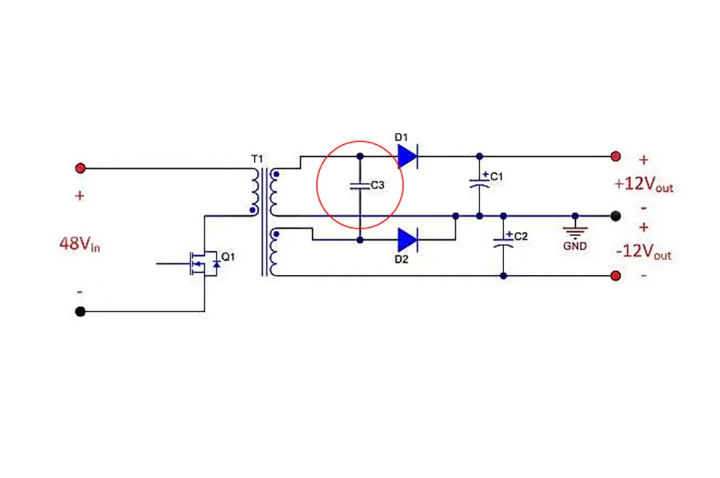
Figure 1A shows a simplified schematic of a 48-V to ±12-V supply in its normal configuration. To implement the technique proposed here, you must first shuffle the secondary connections around a little, as shown in Figure 1B, by adding capacitor C3 and moving diode D2 from the low side of the secondary winding to the high side. Also, notice that the two transformer secondary windings no longer share a common connection. Other than the added capacitor, C3, Figure 1B is electrically equivalent to Figure 1A.


Figure 1
Typical configuration of dual-output flyback supplies (A); reconfiguring and adding a capacitor as shown improves cross-regulation (B).

Figure 2A shows the state of the circuit when Q1 is off and both D1 and D2 are conducting. During this state, the transformer delivers energy to both outputs through the secondary windings. Notice that C3 is connected in parallel with the +12-V output, and thus charges to the same voltage level.

Figure 2B shows the state of the circuit when Q1 is on and both D1 and D2 are reverse-biased and in the off state. During this state, energy is being stored magnetically in the transformer as the primary winding charges from the input voltage. In this state, as long as both secondary windings have the same number of turns, the voltage across C3 is equal to the magnitude of the −12-V output, as described by the equation shown in Figure 2B. As the circuit alternates between these two states, capacitor C3 acts as a charge pump, helping keep the magnitude of both output voltages balanced. This charge-pump effect compensates for voltage imbalances caused by parasitic elements in the circuit. If the two secondary windings have a different number of turns, this technique will not work.


Figure 2
Two states of the circuit: Q1 off, D1 and D2 on (A); Q1 on, D1 and D2 off (B).

Figure 3 shows a simulation schematic modeling the leakage inductances on the primary and secondary windings. As detailed in Power Tips #78, these leakage inductances cause large differences in regulation. The leakage inductance on the primary causes a short duration voltage pedestal to appear on the primary, which couples across to the secondary windings. The leakage inductances on the secondary windings degrade the coupling between the two output voltages.


Figure 3
Schematic of a simulation model to investigate the effects of leakage inductance on output-voltage regulation

Figure 4 shows the voltage and current waveforms in the output diodes when loading the +12-V output with 1 A and the −12-V output with 10 mA. Adding the 1-µF capacitor C3 not only keeps the two outputs well-coupled, but also filters the effects of the voltage pedestal caused by the leakage on the primary winding. Notice the small oscillation on the diode voltage of the more lightly loaded −12-V output. This oscillation is caused by leakage inductances resonating with capacitor C3, and results in a phase shift in the conduction of the −12-V output diode. The current waveform shapes are interesting in that the −12-V current maintains a triangular shape, which subtracts from the +12-V secondary winding current.


Figure 4
Voltage and current waveforms on the output diodes, with the +12-V output loaded at 1 A and the -12 V loaded at 10 mA

The graph of Figure 5 shows the regulation impacts of adding the capacitor. Here, simulations are plotted with different loading conditions on the two outputs, both with and without the added capacitor.

Without the capacitor, the −12-V output voltage rises significantly, as the −12-V load decreases toward zero. With the capacitor, both outputs track each other within 3% across the entire load range. These results are similar to those obtained by using synchronous rectifiers, as detailed in Power Tips #78, but without the penalty of increased RMS winding currents, and with very little added cost or complexity.


Figure 5
Simulation results show how adding a single capacitor greatly improves cross-regulation.

In conclusion, parasitic leakage inductances conspire to degrade regulation in multiple output power supplies. In supplies with dual positive and negative outputs of equal magnitude, adding a single capacitor can vastly improve the regulation.

In multiple output supplies with different output voltage magnitudes, using synchronous rectifiers is probably the best approach for improving cross-regulation.

The next time you are designing a dual-output power supply, consider implementing this simple technique to improve the performance of your design.

For more Power Tips, check out TI’s Power Tips blog series on Power House.


Related

Recent Posts

Researchers Present Hybrid Supercapacitor Zn-Ion Microcapacitors

12.5.2025
9

Supercapacitors Emerge as a Promising Solution to AI-Induced Power Energy Spikes

6.5.2025
69

Murata and NIMS Built New Database of Dielectric Material Properties

5.5.2025
54

Tariffs Crush Sales Sentiment in April 2025 ECST Results

5.5.2025
70

Solid State Polymer Multilayer Capacitors For High Temperature Application

2.5.2025
41

Graphene-Based BOSC Bank Of Supercapacitor Cells

2.5.2025
14

Hybrid Energy Storage System for Nanosatellite Applications

1.5.2025
9

COTS-Plus Bulk Tantalum Capacitor for LEO Flight Platforms

29.4.2025
39

High Energy Density Supercapacitors for Space Applications

28.4.2025
37

Layer-By-Layer Printed Film Dielectrics For Energy Efficient Space Systems

28.4.2025
14

Upcoming Events

May 14
11:00 - 12:00 CEST

Reliable RIGID.flex PCBs for Critical Applications – Made in Europe

May 14
17:00 - 17:30 CEST

Calculating Foil Winding Losses with AI

May 28
16:00 - 17:00 CEST

Power Over Data Line

View Calendar

Popular Posts

  • Buck Converter Design and Calculation

    0 shares
    Share 0 Tweet 0
  • Boost Converter Design and Calculation

    0 shares
    Share 0 Tweet 0
  • SEPIC Converter Design and Calculation

    0 shares
    Share 0 Tweet 0
  • What is a Dielectric Constant and DF of Plastic Materials?

    4 shares
    Share 4 Tweet 0
  • Flyback Converter Design and Calculation

    0 shares
    Share 0 Tweet 0
  • LLC Resonant Converter Design and Calculation

    0 shares
    Share 0 Tweet 0
  • Flying Capacitors Explained

    0 shares
    Share 0 Tweet 0
  • Supercapacitors Emerge as a Promising Solution to AI-Induced Power Energy Spikes

    0 shares
    Share 0 Tweet 0
  • MLCC and Ceramic Capacitors

    0 shares
    Share 0 Tweet 0
  • Ripple Current and its Effects on the Performance of Capacitors

    3 shares
    Share 3 Tweet 0

Newsletter Subscription


Passive Components Blog

© EPCI - Leading Passive Components Educational and Information Site

  • Home
  • Privacy Policy
  • EPCI Membership & Advertisement
  • About

No Result
View All Result
  • Home
  • Knowledge Blog
  • Premium Suppliers

© EPCI - Leading Passive Components Educational and Information Site

This website uses cookies. By continuing to use this website you are giving consent to cookies being used. Visit our Privacy and Cookie Policy.
Go to mobile version