Passive Components Blog
No Result
View All Result
  • Home
  • NewsFilter
    • All
    • Aerospace & Defence
    • Antenna
    • Applications
    • Automotive
    • Capacitors
    • Circuit Protection Devices
    • electro-mechanical news
    • Filters
    • Fuses
    • Inductors
    • Industrial
    • Integrated Passives
    • inter-connect news
    • Market & Supply Chain
    • Market Insights
    • Medical
    • Modelling and Simulation
    • New Materials & Supply
    • New Technologies
    • Non-linear Passives
    • Oscillators
    • Passive Sensors News
    • Resistors
    • RF & Microwave
    • Telecommunication
    • Weekly Digest

    Bourns Extends Rotational Life Option for its Guitar Potentiometer

    Modeling and Simulation of Leakage Inductance

    Power Inductor Considerations for AI High Power Computing – Vishay Video

    TAIYO YUDEN Releases Compact SMD Power Inductors for Automotive Application

    Fischer Releases High Vibration Robust Ratchet Locking USB-C Connector System

    Littelfuse Unveils High-Use Tactile Switches with 2 Million Cycle Lifespan

    KYOCERA AVX Releases Compact High-Directivity Couplers

    Supercapacitors Emerge as a Promising Solution to AI-Induced Power Energy Spikes

    Wk 18 Electronics Supply Chain Digest

    Trending Tags

    • Ripple Current
    • RF
    • Leakage Current
    • Tantalum vs Ceramic
    • Snubber
    • Low ESR
    • Feedthrough
    • Derating
    • Dielectric Constant
    • New Products
    • Market Reports
  • VideoFilter
    • All
    • Antenna videos
    • Capacitor videos
    • Circuit Protection Video
    • Filter videos
    • Fuse videos
    • Inductor videos
    • Inter-Connect Video
    • Non-linear passives videos
    • Oscillator videos
    • Passive sensors videos
    • Resistor videos

    Modeling and Simulation of Leakage Inductance

    Power Inductor Considerations for AI High Power Computing – Vishay Video

    Coupled Inductors in Multiphase Boost Converters

    VPG Demonstrates Precision Resistor in Cryogenic Conditions

    Comparison Testing of Chip Resistor Technologies Under High Vibration

    EMC Challenges for High Speed Signal Immunity and Low EMI

    MOSFET Gate Drive Resistors Power Losses

    Modified Magnetic Reluctance Equivalent Circuit and its Implications

    Improving Common Mode Noise Reduction while Decreasing BOM

    Trending Tags

    • Capacitors explained
    • Inductors explained
    • Resistors explained
    • Filters explained
    • Application Video Guidelines
    • EMC
    • New Products
    • Ripple Current
    • Simulation
    • Tantalum vs Ceramic
  • Knowledge Blog
  • Suppliers
    • Who is Who
  • Events
No Result
View All Result
Passive Components Blog
No Result
View All Result

Input protection filters out the risks in power converters

12.7.2017
Reading Time: 5 mins read
A A

source: Electronics Weekly article

Input protection for switched mode inverters and converters affects an increasing number of sectors, writes Martin Keenan of Avnet Abacus.

RelatedPosts

Bourns Extends Rotational Life Option for its Guitar Potentiometer

Modeling and Simulation of Leakage Inductance

Power Inductor Considerations for AI High Power Computing – Vishay Video

Switched mode inverters and converters form the heart of many modern power applications including ‘smart’ motor drives, solar power, UPS systems, high power AC-DC converters and many more.

All these applications must meet statutory and practical requirements for input electromagnetic interference (EMI) filtering and protection against injury to personnel or damage to equipment.

A typical requirement for a power converter starts with a list of statutory standards for safety and electromagnetic compatibility (EMC). ‘Volts and amps’ come way down the list and are sometimes not even known for certain.

Standard definitions
At least safety and EMC specifications can be defined early on.

Safety is often the IT standard UL/EN 60950-1 – or its upcoming replacement EN62368-1 – and EMC is often the EN61000 series covering conducted and radiated emissions; immunity to transients and surges on the power lines; and immunity to electromagnetic radiation and electrostatic discharge.

Particular applications such as medical or motor drives have their own specifications, often based on these standards.

Input filtering to meet the EMC specifications needs to be designed with an eye on safety, as the requirements can be interdependent. For example, filtering protects against transients that could damage safety insulation and AC leakage current requirements restrict the value of some EMC components. An ideal input filter takes all this into account without degrading the basic functionality of the converter.

power, input filter

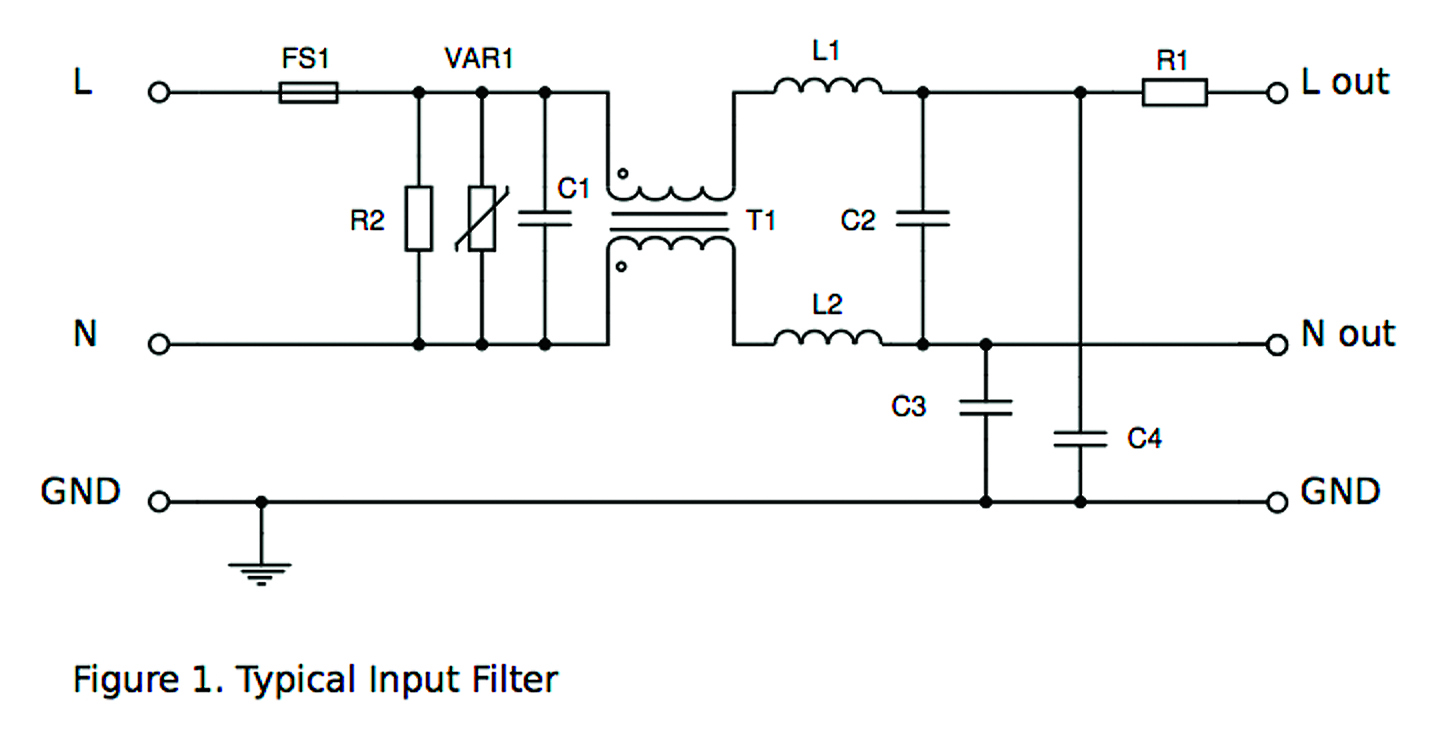
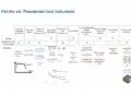
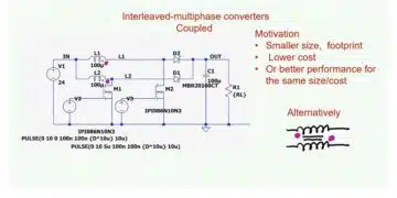
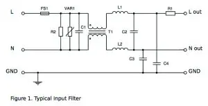
Figure 1: A schematic illustrating the structure of a typical input filter

A simplistic filter design, such as shown in Figure 1 above, takes all the requirements one by one and includes discrete components to meet the overall specification.

In the schematic, Figure 1 the functions are:

  • L1, L2, C1 and C2 attenuate differential mode (DM) noise
  • T1, C3 and C4 reduce common mode (CM) noise
  • VAR1 absorbs energy from input transients and surges
  • R1 limits start-up inrush current
  • R2 discharges C1 and C2 on power down
  • FS1 protects against downstream shorts

The EMI limits for conducted interference, typically using standard CISPR22 and its derivative EN55022, use a test setup using a line impedance stabiliser network (LISN) (Figure 2) which registers the addition and subtraction of differential and common mode currents, so a filter must adequately attenuate both CM and DM noise to meet the limits.

Power, line impedance stabiliser network

Figure 2: A schematic illustrating the structure of a line impedance stabiliser network

At low power, filtering is often minimal. A peek inside a modern mobile phone charger, for example, will show few specific EMC components while still meeting statutory requirements.

The push for lower cost and simplicity has driven design techniques to minimise EMI at source by using ‘soft switching’ and optimum layout for EMC. CM noise, for example, often results when current from switching devices couples into grounded heatsinks. If a primary heatsink can be isolated from ground, AC mains leakage is also reduced, an example of safety and EMC interacting.

A typical filter explained
At low power, T1 is often unnecessary, but could be wound with high leakage inductance to effectively include L1 and L2.

A fusible resistor can combine R1 and FS1, and C2 may be omitted, depending on EMI levels. Meanwhile, VAR1 could be omitted depending on the circuit impedances and application environment.

In ‘Class II’ or earth-free applications, C3 and C4 would not be fitted although similar capacitors may be fitted from input 0V to output ground.

So let us consider the function of each component in turn:

  • FS1 is a ‘fast blow’ type, with agency ratings for the input voltage and with rating adequate to pass the normal running current with a guarantee to open with downstream shorts that might cause a shock or fire hazard. In primary circuits, creepage and clearance distances can sometimes be reduced if shorts across the connections are guaranteed to open the fuse. DC input converters require fuse types that ‘self-extinguish’ arcs during opening, typically sand-filled.
  • VAR1 in extreme cases has to absorb significant energy and might be supplemented by a Transorb or even gas discharge tubes. Again, its presence allows the downstream circuitry to have reduced creepage and clearances if preceded by such a voltage limiting component. Of course, VAR1 must be rated for the highest line input voltage and must absorb the specified transients.
  • At power down, C1 and C2 have to discharge to a safe voltage within a specified time, R2 performing this function. Its dissipation in normal operation can, however, exceed target levels for no-load power consumption, so schemes have been introduced to actively disconnect R2 until needed. A common mistake is to select a general-purpose resistor for R2. As it is across the line it needs to be high voltage type. However, if the values of C1 and C2 together are less than 100nF, R2 can be omitted.
  • DM emissions are attenuated by L1, L2 and C1 and C2 ‘X’ capacitors which also help to absorb transients from the input supply. Relatively high capacitance is often needed, typically 500nF, and they must be rated for the continuous input voltage and over-voltages on the line. These are set by the ‘overvoltage category’ of the application requiring either ‘X1’ types rated at 4kV test or ‘X2’ types rated at 2.5kV test. L1 and L2 see full line current, so they are typically small value iron powder toroidal cores.
  • CM emissions are reduced by C3 and C4 ‘Y’ capacitors providing a low‑impedance path for noise to circulate inside the converter. Again, the parts must be chosen according to line ‘overvoltage category’, and are either ‘Y1’ types rated at 8kV test or ‘Y2’ types at 5kV test. The value of Y capacitors is limited because under the fault condition of a protective earth connection going open, a metal chassis would connect to live through the capacitors. The capacitance must then be limited to allow a maximum ‘touch’ current to flow as set by the standards and application, being as low as 10µA in sensitive medical environments.
  • T1, with its ‘current compensated’ windings, provides high impedance to CM noise without saturation from line current and is a ferrite toroid or E-core with isolation between windings.
  • Inrush current is limited by R1 and at higher power is often an NTC thermistor to avoid standing losses.
    At even higher power, a triac or possibly a relay may be used to short out the resistor after the surge has passed, to reduce dissipation.

Commercially available products suitable for elements of filter networks include TDK-EPCOS’ series S, E2/E3(K1) and Q for varistors, S364x and S464x for thermistors, B3292x for X2 capacitors and B3202x for Y2 capacitors.

They provide the B8245/6/7/8 series of common mode chokes, while their range of ferrite cores can be used for custom solutions.

Complete filter modules are also available in, for example, TDK’s B84143 series.

Related

Recent Posts

Power Inductor Considerations for AI High Power Computing – Vishay Video

9.5.2025
4

TAIYO YUDEN Releases Compact SMD Power Inductors for Automotive Application

9.5.2025
1

Littelfuse Unveils High-Use Tactile Switches with 2 Million Cycle Lifespan

9.5.2025
2

Supercapacitors Emerge as a Promising Solution to AI-Induced Power Energy Spikes

6.5.2025
36

YAGEO Releases High Current SMD Common Mode Choke With Shape Core Construction

5.5.2025
22

Tariffs Crush Sales Sentiment in April 2025 ECST Results

5.5.2025
61

Solid State Polymer Multilayer Capacitors For High Temperature Application

2.5.2025
32

Würth Elektronik Offers New Power Supplies Development Kit

29.4.2025
37

Bourns Extends Shielded Power Inductors by Four New Series

29.4.2025
18

binder Releases M12 Robust Stainless Steel Locking L- and T-coded Connectors

28.4.2025
5

Upcoming Events

May 14
11:00 - 12:00 CEST

Reliable RIGID.flex PCBs for Critical Applications – Made in Europe

May 14
17:00 - 17:30 CEST

Calculating Foil Winding Losses with AI

May 28
16:00 - 17:00 CEST

Power Over Data Line

View Calendar

Popular Posts

  • Buck Converter Design and Calculation

    0 shares
    Share 0 Tweet 0
  • Boost Converter Design and Calculation

    0 shares
    Share 0 Tweet 0
  • Flyback Converter Design and Calculation

    0 shares
    Share 0 Tweet 0
  • What is a Dielectric Constant and DF of Plastic Materials?

    4 shares
    Share 4 Tweet 0
  • Dual Active Bridge (DAB) Topology Explained

    0 shares
    Share 0 Tweet 0
  • Ripple Current and its Effects on the Performance of Capacitors

    3 shares
    Share 3 Tweet 0
  • Solid State Polymer Multilayer Capacitors For High Temperature Application

    0 shares
    Share 0 Tweet 0
  • LLC Resonant Converter Design and Calculation

    0 shares
    Share 0 Tweet 0
  • SEPIC Converter Design and Calculation

    0 shares
    Share 0 Tweet 0
  • MLCC Case Sizes Standards Explained

    0 shares
    Share 0 Tweet 0

Newsletter Subscription


Passive Components Blog

© EPCI - Leading Passive Components Educational and Information Site

  • Home
  • Privacy Policy
  • EPCI Membership & Advertisement
  • About

No Result
View All Result
  • Home
  • Knowledge Blog
  • Premium Suppliers

© EPCI - Leading Passive Components Educational and Information Site

This website uses cookies. By continuing to use this website you are giving consent to cookies being used. Visit our Privacy and Cookie Policy.
Go to mobile version