Passive Components Blog
No Result
View All Result
  • Home
  • NewsFilter
    • All
    • Aerospace & Defence
    • Antenna
    • Applications
    • Automotive
    • Capacitors
    • Circuit Protection Devices
    • electro-mechanical news
    • Filters
    • Fuses
    • Inductors
    • Industrial
    • Integrated Passives
    • inter-connect news
    • Market & Supply Chain
    • Market Insights
    • Medical
    • Modelling and Simulation
    • New Materials & Supply
    • New Technologies
    • Non-linear Passives
    • Oscillators
    • Passive Sensors News
    • Resistors
    • RF & Microwave
    • Telecommunication
    • Weekly Digest

    Bourns Extends Rotational Life Option for its Guitar Potentiometer

    Modeling and Simulation of Leakage Inductance

    Power Inductor Considerations for AI High Power Computing – Vishay Video

    TAIYO YUDEN Releases Compact SMD Power Inductors for Automotive Application

    Fischer Releases High Vibration Robust Ratchet Locking USB-C Connector System

    Littelfuse Unveils High-Use Tactile Switches with 2 Million Cycle Lifespan

    KYOCERA AVX Releases Compact High-Directivity Couplers

    Supercapacitors Emerge as a Promising Solution to AI-Induced Power Energy Spikes

    Wk 18 Electronics Supply Chain Digest

    Trending Tags

    • Ripple Current
    • RF
    • Leakage Current
    • Tantalum vs Ceramic
    • Snubber
    • Low ESR
    • Feedthrough
    • Derating
    • Dielectric Constant
    • New Products
    • Market Reports
  • VideoFilter
    • All
    • Antenna videos
    • Capacitor videos
    • Circuit Protection Video
    • Filter videos
    • Fuse videos
    • Inductor videos
    • Inter-Connect Video
    • Non-linear passives videos
    • Oscillator videos
    • Passive sensors videos
    • Resistor videos

    Modeling and Simulation of Leakage Inductance

    Power Inductor Considerations for AI High Power Computing – Vishay Video

    Coupled Inductors in Multiphase Boost Converters

    VPG Demonstrates Precision Resistor in Cryogenic Conditions

    Comparison Testing of Chip Resistor Technologies Under High Vibration

    EMC Challenges for High Speed Signal Immunity and Low EMI

    MOSFET Gate Drive Resistors Power Losses

    Modified Magnetic Reluctance Equivalent Circuit and its Implications

    Improving Common Mode Noise Reduction while Decreasing BOM

    Trending Tags

    • Capacitors explained
    • Inductors explained
    • Resistors explained
    • Filters explained
    • Application Video Guidelines
    • EMC
    • New Products
    • Ripple Current
    • Simulation
    • Tantalum vs Ceramic
  • Knowledge Blog
  • Suppliers
    • Who is Who
  • Events
No Result
View All Result
Passive Components Blog
No Result
View All Result

Active vs Passive EMI filtering

8.8.2022
Reading Time: 5 mins read
A A

Design engineers working on low-electromagnetic interference (EMI) applications typically face two major challenges: the need to reduce the EMI of their designs while also shrinking solution size. Orlando Murray and co-author Tim Hegarty compare passive and active EMI filtering approach in their article published by ELE Times Bureau.

Front-end passive filtering to mitigate conducted EMI generated by the switching power supply ensures compliance with conducted EMI standards, but this method can be at odds with the need to increase the power density of low-EMI designs, especially given the adverse effects of higher switching speeds on the overall EMI signature. These passive filters tend to be bulky and can occupy as much as 30% of the total volume of the power solution. Therefore, minimizing the volume of the EMI filter while increasing power density remains a priority for system designers.

RelatedPosts

Inductor Selection Guide for BMS Battery Management System

EMI Suppression by PP Film Capacitor in OBC Automotive Application

EMC Issues and How to Avoid it

Active EMI filtering (AEF) technology, a relatively new approach to EMI filtering, attenuates EMI and enables engineers to achieve a significant reduction in passive filter size and cost, along with improved EMI performance. To illustrate the key benefits that AEF can offer in terms of EMI performance and space savings, in this technical article I’ll review results from an automotive synchronous buck controller design with integrated AEF functionality.

EMI filtering

Passive filtering reduces the conducted emissions of a power electronic circuit by using inductors and capacitors to create an impedance mismatch in the EMI current path. In contrast, active filtering senses the voltage at the input bus and produces a current of opposite phase that directly cancels with the EMI current generated by a switching stage.

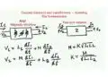
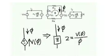
Within this context, take a look at the simplified passive and active filter circuits in Figure 1, where iN and ZN respectively denote the current source and impedance of the Norton-equivalent circuit for differential-mode noise of a DC/DC regulator.

Figure 1: Conventional passive filtering (a) and active filtering (b) circuit implementations

The active EMI filter configured with voltage sense and current cancellation (VSCC) in Figure 1b uses an operational-amplifier (op-amp) circuit as a capacitive multiplier to replace the filter capacitor (CF) in the passive design. The active filter sensing, injection and compensation impedances as shown use relatively low capacitance values with small component footprints to design a gain term denoted as GOP. The effective active capacitance is set by the op-amp circuit gain and an injection capacitor (CINJ).

Figure 1 includes expressions for the effective filter cutoff frequencies. The effective GOP enables an active design with reduced inductor and capacitor values and a cutoff frequency equivalent to that of the passive implementation.

Improved filtering performance

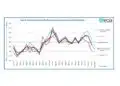
Figure 2 compares passive and active EMI filter designs based on conducted EMI tests to meet the Comité International Spécial des Perturbations Radioélectriques (CISPR) 25 Class 5 standard using peak and average detectors. Each design uses a power stage based on the LM25149-Q1 synchronous buck DC/DC controller, providing an output of 5 V and 6 A from an automotive battery input of 13.5 V. The switching frequency is 440 kHz.

Figure 2: Comparing a passive filter solution (a) and active filter design (b) using equivalent power-stage operating conditions

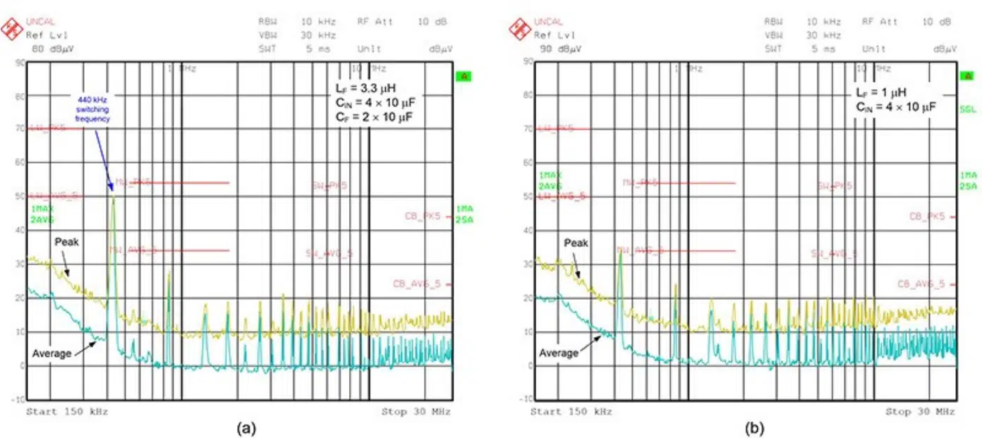
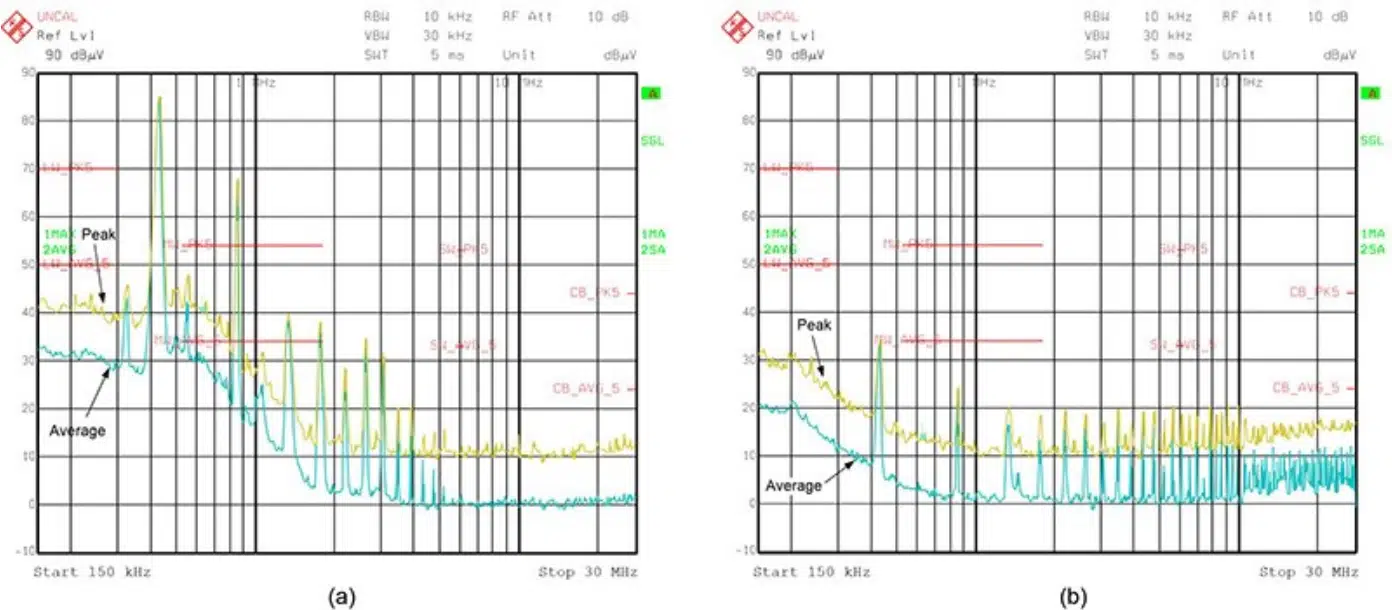
Figure 3 presents the results when enabling and disabling the AEF circuit. The active EMI filter shows much better low- and medium-frequency attenuation compared to the unfiltered or raw noise signature. The fundamental frequency component at 440 kHz has its peak EMI level reduced by almost 50 dB, making it much easier for designers to meet strict EMI requirements.
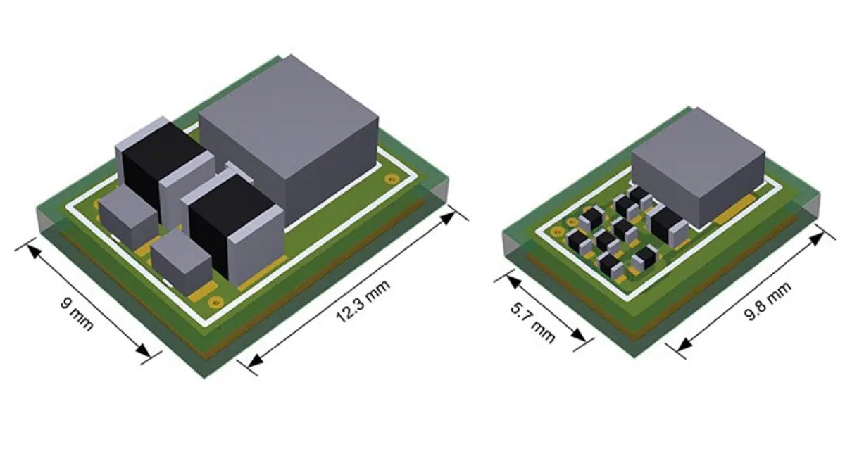
Figure 3: Comparing filtering performance when AEF is disabled (a) and enabled (b)

PCB space savings

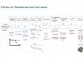
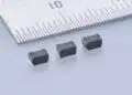
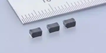
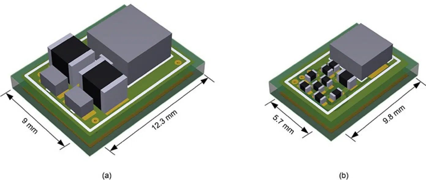
Figure 4 offers a printed circuit board (PCB) layout comparison of the passive and active filter stages that provided the results in Figure 2. The inductor footprint reduces from 5 mm by 5 mm to 4 mm by 4 mm. In addition, two 1210 capacitors that derate significantly with applied voltage are replaced by several small, stable-valued 0402 components for AEF sensing, injection and compensation. This filter solution decreases the footprint by nearly 50%, while the volume decreases by over 75%.

Figure 4: PCB layout size comparison of passive (a) and active (b) filter designs

Passive component advantages

As I mentioned, the lower filter inductance value for AEF reduces the footprint and cost compared to the inductor in a passive filter design. Moreover, a physically smaller inductor typically has a winding geometry with a lower parasitic winding capacitance and higher self-resonant frequency, leading to better filtering performance in the higher conducted frequency range for CISPR 25: 30 MHz to 108 MHz.

Some automotive designs require two input capacitors connected in series for fail-safe robustness when connected directly across the battery-supply rail. As a result, the active circuit can support additional space savings, as small 0402/0603 sensing and injection capacitors connect in series to replace multiple 1210 capacitors. The smaller capacitors simplify component procurement as components are readily available and not supply-constrained.

Conclusion

Amid a continual focus on EMI, particularly in automotive applications, an active filter using voltage sense and current injection enables a low EMI signature and ultimately leads to a reduced footprint and volume, as well as an improved solution cost. The integration of an AEF circuit with a synchronous buck controller helps resolve the trade-offs between low EMI and high power density in DC/DC regulator applications.

Related

Source: ELE Times

Recent Posts

Modeling and Simulation of Leakage Inductance

9.5.2025
1

Power Inductor Considerations for AI High Power Computing – Vishay Video

9.5.2025
4

TAIYO YUDEN Releases Compact SMD Power Inductors for Automotive Application

9.5.2025
1

Supercapacitors Emerge as a Promising Solution to AI-Induced Power Energy Spikes

6.5.2025
34

YAGEO Releases High Current SMD Common Mode Choke With Shape Core Construction

5.5.2025
21

Murata and NIMS Built New Database of Dielectric Material Properties

5.5.2025
43

Tariffs Crush Sales Sentiment in April 2025 ECST Results

5.5.2025
59

Solid State Polymer Multilayer Capacitors For High Temperature Application

2.5.2025
29

Graphene-Based BOSC Bank Of Supercapacitor Cells

2.5.2025
13

Hybrid Energy Storage System for Nanosatellite Applications

1.5.2025
9

Upcoming Events

May 14
11:00 - 12:00 CEST

Reliable RIGID.flex PCBs for Critical Applications – Made in Europe

May 28
16:00 - 17:00 CEST

Power Over Data Line

View Calendar

Popular Posts

  • Buck Converter Design and Calculation

    0 shares
    Share 0 Tweet 0
  • Boost Converter Design and Calculation

    0 shares
    Share 0 Tweet 0
  • Tariffs Crush Sales Sentiment in April 2025 ECST Results

    0 shares
    Share 0 Tweet 0
  • Flyback Converter Design and Calculation

    0 shares
    Share 0 Tweet 0
  • What is a Dielectric Constant and DF of Plastic Materials?

    4 shares
    Share 4 Tweet 0
  • LLC Resonant Converter Design and Calculation

    0 shares
    Share 0 Tweet 0
  • Dual Active Bridge (DAB) Topology Explained

    0 shares
    Share 0 Tweet 0
  • Ripple Current and its Effects on the Performance of Capacitors

    3 shares
    Share 3 Tweet 0
  • SEPIC Converter Design and Calculation

    0 shares
    Share 0 Tweet 0
  • Flying Capacitors Explained

    0 shares
    Share 0 Tweet 0

Newsletter Subscription


Passive Components Blog

© EPCI - Leading Passive Components Educational and Information Site

  • Home
  • Privacy Policy
  • EPCI Membership & Advertisement
  • About

No Result
View All Result
  • Home
  • Knowledge Blog
  • Premium Suppliers

© EPCI - Leading Passive Components Educational and Information Site

This website uses cookies. By continuing to use this website you are giving consent to cookies being used. Visit our Privacy and Cookie Policy.
Go to mobile version