Passive Components Blog
No Result
View All Result
  • Home
  • NewsFilter
    • All
    • Aerospace & Defence
    • Antenna
    • Applications
    • Automotive
    • Capacitors
    • Circuit Protection Devices
    • electro-mechanical news
    • Filters
    • Fuses
    • Inductors
    • Industrial
    • Integrated Passives
    • inter-connect news
    • Market & Supply Chain
    • Market Insights
    • Medical
    • Modelling and Simulation
    • New Materials & Supply
    • New Technologies
    • Non-linear Passives
    • Oscillators
    • Passive Sensors News
    • Resistors
    • RF & Microwave
    • Telecommunication
    • Weekly Digest

    Power Inductor Considerations for AI High Power Computing – Vishay Video

    TAIYO YUDEN Releases Compact SMD Power Inductors for Automotive Application

    Fischer Releases High Vibration Robust Ratchet Locking USB-C Connector System

    Littelfuse Unveils High-Use Tactile Switches with 2 Million Cycle Lifespan

    KYOCERA AVX Releases Compact High-Directivity Couplers

    Supercapacitors Emerge as a Promising Solution to AI-Induced Power Energy Spikes

    Wk 18 Electronics Supply Chain Digest

    YAGEO Releases High Current SMD Common Mode Choke With Shape Core Construction

    Murata and NIMS Built New Database of Dielectric Material Properties

    Trending Tags

    • Ripple Current
    • RF
    • Leakage Current
    • Tantalum vs Ceramic
    • Snubber
    • Low ESR
    • Feedthrough
    • Derating
    • Dielectric Constant
    • New Products
    • Market Reports
  • VideoFilter
    • All
    • Antenna videos
    • Capacitor videos
    • Circuit Protection Video
    • Filter videos
    • Fuse videos
    • Inductor videos
    • Inter-Connect Video
    • Non-linear passives videos
    • Oscillator videos
    • Passive sensors videos
    • Resistor videos

    Power Inductor Considerations for AI High Power Computing – Vishay Video

    Coupled Inductors in Multiphase Boost Converters

    VPG Demonstrates Precision Resistor in Cryogenic Conditions

    Comparison Testing of Chip Resistor Technologies Under High Vibration

    EMC Challenges for High Speed Signal Immunity and Low EMI

    MOSFET Gate Drive Resistors Power Losses

    Modified Magnetic Reluctance Equivalent Circuit and its Implications

    Improving Common Mode Noise Reduction while Decreasing BOM

    Die and Wire PCB Bonding Explained

    Trending Tags

    • Capacitors explained
    • Inductors explained
    • Resistors explained
    • Filters explained
    • Application Video Guidelines
    • EMC
    • New Products
    • Ripple Current
    • Simulation
    • Tantalum vs Ceramic
  • Knowledge Blog
  • Suppliers
    • Who is Who
  • Events
No Result
View All Result
Passive Components Blog
No Result
View All Result

Linear Variable Differential Transformers LVDTs Explained

4.3.2025
Reading Time: 7 mins read
A A

Linear variable differential transformers (LVDT) are an electromechanical transducers that senses the mechanical displacement of a core and produces a proportional AC voltage at the output. This article by Steve Arar explain LVDT basics, including structure, circuit, transfer function, linear range, sensitivity, and more.

High resolution (infinite in theory), high linearity (0.5% or better), high sensitivity and zero mechanical friction are some of the important features of the LVDT devices.

RelatedPosts

Power Inductor Considerations for AI High Power Computing – Vishay Video

TAIYO YUDEN Releases Compact SMD Power Inductors for Automotive Application

Fischer Releases High Vibration Robust Ratchet Locking USB-C Connector System

In this article, we’ll look at the structure and working principles of LVDTs. We’ll also examine three important parameters of these sensors: linear range, linearity error, and sensitivity.  

Structure of an LVDT

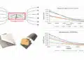
Figure 1 shows the cutaway view and circuit model of a basic LVDT. It consists of one primary winding coupled to two secondary windings through a movable core. As the magnetically permeable core moves, the magnetic coupling between the primary and each of the secondary windings changes accordingly. This produces position-dependent voltage signals across the two windings that can be used to determine the position of an object.

Figure 1(a). Cutaway view of an LVDT. Image courtesy of Honeywell
Figure 1(b). Circuit model of an LVDT

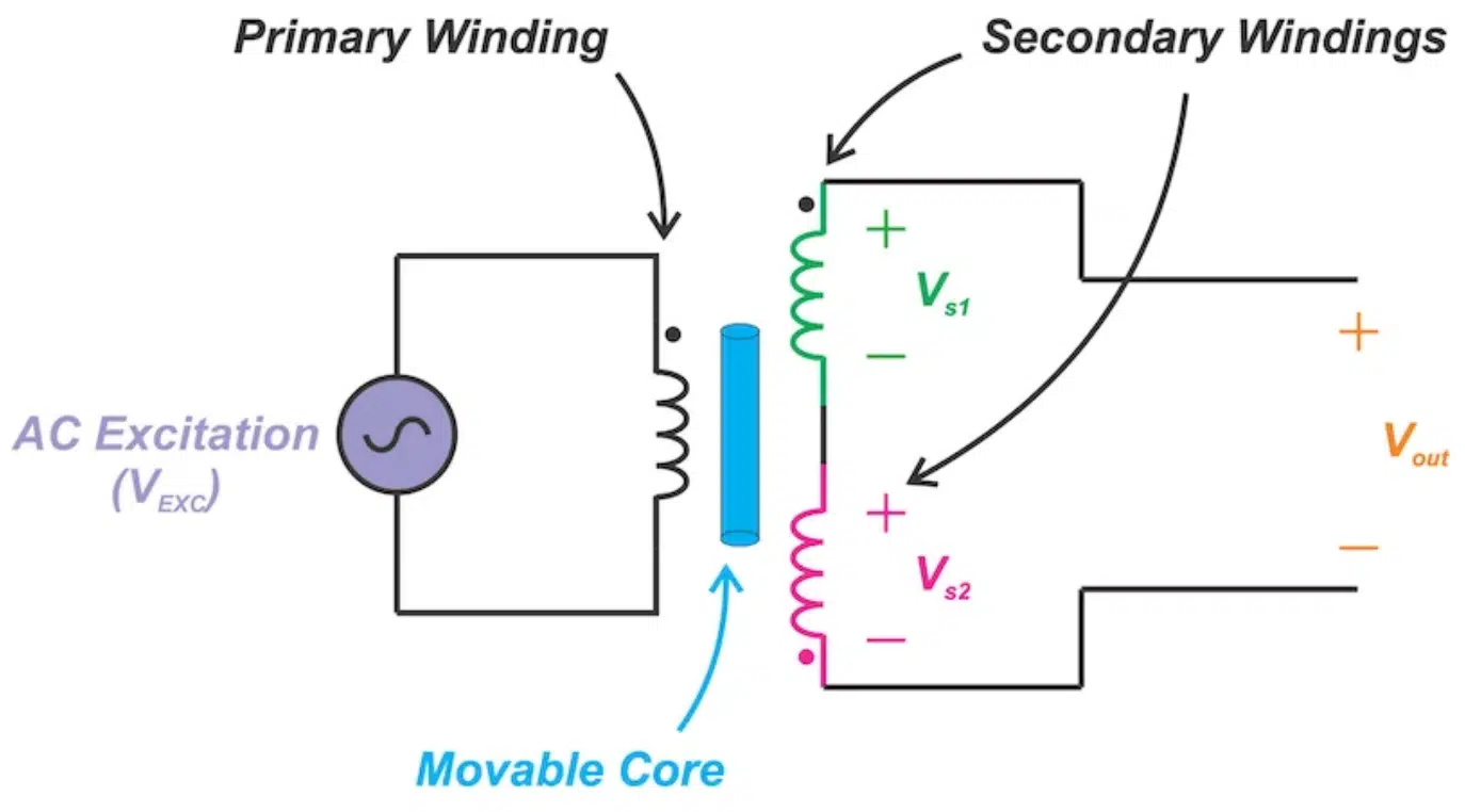
The two secondary windings are series-opposed meaning that they are connected in series but wound in opposite directions. The core, typically through a non-ferromagnetic rod, attaches to the object whose movement is being measured and the coil assembly is typically fixed to a stationary form. 

How Does It Work?

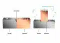
Figure 2 shows how a perfectly centered core ideally produces a zero output. The input is excited by an AC voltage of appropriate frequency (VEXC). Since the two secondaries are wound symmetrically on the two sides of the primary coil, a centered core leads to equal magnetic coupling from the primary to the two secondaries. With the secondary windings being series-opposed, equal voltages with opposite polarities will be induced across the two secondaries (Vs1 = -Vs2). Hence, the voltages of the two windings will cancel out and we’ll have an overall output of zero (Vout = 0). 

Figure 2. LVDT with a perfectly centered core
Figure 3. LVDT with the core moved upward
Figure 4. LVDT with the core moved downward

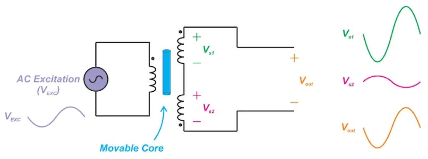
When the core is displaced upward as shown in Figure 3, the coupling between the primary and the first secondary becomes stronger. This leads to a larger AC voltage across the first secondary compared to the second secondary (|Vs1| > |Vs2|) and a non-zero output (Vout). Note that the output is in phase with Vs1 but its amplitude is relatively smaller. With the example depicted in Figure 3, the output should be ideally in-phase with VEXC when the core experiences an upward displacement.

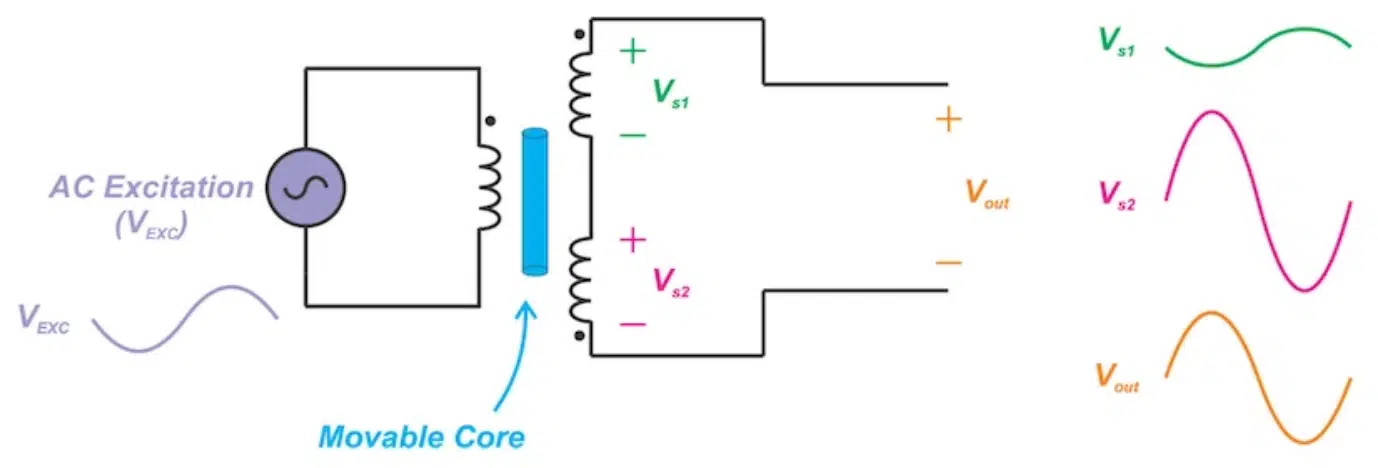
The typical waveforms for the downward displacement of the core is shown in Figure 4. In this case, the magnetic coupling between the primary and the second secondary increases leading to |Vs2| > |Vs1|. As you can see, we’ll have a non-zero Vout that is ideally 180° out-of-phase with respect to the excitation voltage.

Figure 5. Image courtesy of Ramón Pallás-Areny and John G. Webster, Sensors and Signal Conditioning

Transfer Function

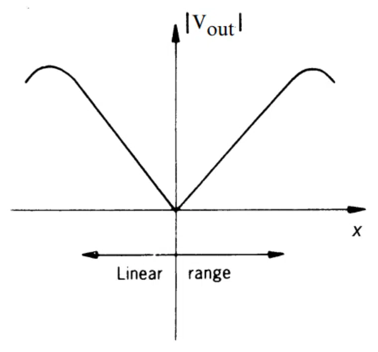
Figure 5 shows the transfer function of a typical LVDT. The x-axis is the core displacement from the center. The y-axis is the amplitude of the output AC voltage.

At the origin (x = 0), the output is ideally zero. As the core is moved off center in either direction, the amplitude of the output increases linearly with the core displacement. Note that measuring only the amplitude of the output, we cannot determine whether the core is displaced to the left or to the right. We need to know both the amplitude and phase of the output. 

Linear Range

As shown in Figure 5, an LVDT exhibits a linear transfer function only over a limited range of the core displacement. This is specified as the linear range of the LVDT.

Why does the device stop having a linear relationship beyond this range?

We can imagine that, when the core displacement from the null position goes beyond a certain value, the magnetic flux that gets to couple to the core from the primary winding reduces. This, consequently, leads to a reduction in the voltage that appears across the corresponding secondary winding. The maximum distance that the core can travel from its null position while having a linear transfer function is referred to as the full-scale displacement. 

Broad ranges of LVDTs are available covering displacement ranges as little as ±100 μm to ±25 cm. LVDTs capable of measuring larger ranges also find use in laboratory, industrial and submersible environments.

Linearity Error

The plot of the LVDT output versus the core displacement is not a perfect straight line even in the linear range. The output can slightly deviate from the straight line constructed to have the best fit to the output data.

One mechanism that can lead to non-linearity in the nominal linear range of the device is saturation of the magnetic material. This can produce the 3rd harmonic component even when the core is at the null position. This harmonic can be suppressed by applying a low-pass filter to the LVDT output.

The maximum deviation of the LVDT output from the expected straight line fit is considered as the linearity error. Linearity error is typically expressed as a +/-  percentage of the full-range output. For example, the E-100 LVDT from Measurement Specialties, Inc., has a maximum linearity error of ±0.5% of full-scale range.

Sensitivity

Sensitivity or transfer ratio allows us to relate the output voltage to the core displacement. To determine the sensitivity, we energize the primary at the recommended drive level (3 VRMS for E-100 LVDT) and move the core off the null position by the full-scale displacement. Now, we measure the voltages across the two secondary windings to find the overall output voltage (Vout). Substituting these values in the following equation, we can find the LVDT sensitivity:

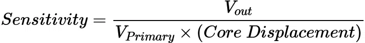
Sensitivity is usually specified in terms of millivolt output per Volt of excitation per thousandths of an inch core displacement (mV/V/mil). For example, the sensitivity of the E-100 is 2.4 mV/V/mil. Having sensitivity, we can determine the required gain of the signal conditioning circuitry.

featured image source: Honeywell

Related

Source: All About Circuits

Recent Posts

Power Inductor Considerations for AI High Power Computing – Vishay Video

9.5.2025
4

TAIYO YUDEN Releases Compact SMD Power Inductors for Automotive Application

9.5.2025
1

YAGEO Releases High Current SMD Common Mode Choke With Shape Core Construction

5.5.2025
21

Murata and NIMS Built New Database of Dielectric Material Properties

5.5.2025
43

Tariffs Crush Sales Sentiment in April 2025 ECST Results

5.5.2025
59

Würth Elektronik Offers New Power Supplies Development Kit

29.4.2025
37

Bourns Extends Shielded Power Inductors by Four New Series

29.4.2025
18

Shielding Cabinets

29.4.2025
17

Magnetic Shielding and Magnetic Shielding Sheets

29.4.2025
25

Corrosion its Development and Prevention

26.4.2025
25

Upcoming Events

May 14
11:00 - 12:00 CEST

Reliable RIGID.flex PCBs for Critical Applications – Made in Europe

May 28
16:00 - 17:00 CEST

Power Over Data Line

View Calendar

Popular Posts

  • Buck Converter Design and Calculation

    0 shares
    Share 0 Tweet 0
  • Boost Converter Design and Calculation

    0 shares
    Share 0 Tweet 0
  • Tariffs Crush Sales Sentiment in April 2025 ECST Results

    0 shares
    Share 0 Tweet 0
  • Flyback Converter Design and Calculation

    0 shares
    Share 0 Tweet 0
  • LLC Resonant Converter Design and Calculation

    0 shares
    Share 0 Tweet 0
  • Dual Active Bridge (DAB) Topology Explained

    0 shares
    Share 0 Tweet 0
  • What is a Dielectric Constant and DF of Plastic Materials?

    4 shares
    Share 4 Tweet 0
  • Ripple Current and its Effects on the Performance of Capacitors

    3 shares
    Share 3 Tweet 0
  • SEPIC Converter Design and Calculation

    0 shares
    Share 0 Tweet 0
  • Flying Capacitors Explained

    0 shares
    Share 0 Tweet 0

Newsletter Subscription


Passive Components Blog

© EPCI - Leading Passive Components Educational and Information Site

  • Home
  • Privacy Policy
  • EPCI Membership & Advertisement
  • About

No Result
View All Result
  • Home
  • Knowledge Blog
  • Premium Suppliers

© EPCI - Leading Passive Components Educational and Information Site

This website uses cookies. By continuing to use this website you are giving consent to cookies being used. Visit our Privacy and Cookie Policy.
Go to mobile version