


DC-Link capacitors for DC filtering and energy storage are expected to operate at higher temperatures, in more extreme conditions, and for longer lifetimes, than ever before. Automotive applications are leading those demands for better performance, but most existing power box, DC-link film technologies are not suitable for these applications and struggle under those severe conditions.
Vehicles primarily use electric compressors in two ways: in air conditioning and electric turbocharger systems (E-turbo). The circuit design for each of these applications is similar, as is the harsh condition in which these systems must operate.
Electric Compressor Application and DC-Link Capacitor Requirements
E-Turbo Application
For our application, we will specifically consider an electronic-driven turbocharger rather than one mechanically driven by belts (often called “superchargers”) or exhaust airflow. E-turbos have particular and obvious advantages over traditional turbochargers in hybrid electric vehicles, given their significant electrical power.
The main goal of an E-turbo is to run the system more efficiently and provide a faster response during idle or low RPM conditions. They accomplish this by positively pressurizing the air at the intake to the combustion chambers, forcing more air into the chamber for each combustion, increasing the engine’s efficiency.
The challenge for the E-turbo application is that much of the electronics used to monitor and control these devices must reside in the engine compartment. Engine compartments are high heat, high humidity, high vibration – the very definition of harsh environments. Any components used must be capable of withstanding those harsh conditions and thriving in them. They must be as small as possible and maintain a long and reliable life.
HVAC Compressors Application
EV and HEV electric compressors use an inverter circuit to convert a high DC voltage to an AC voltage that powers the electric induction motor of the HVAC pump. Fundamentally, this circuit involves an EMI/safety stage, a DC-Link capacitor, and then a MOSFET inverter stage. Trends in EV and HEV HVAC components include simplification, miniaturization, and increased power close to the compressor exposed to high operating temperatures. Some of the critical applications of this type of HVAC compressor include electric water heaters, air heaters, and coolant heaters that control the temperature condition of the battery and interior of the vehicle.
The Role of the DC-Link Capacitor
The DC-Link capacitor is found in power converters (in the DC part of the circuit between the input and output stages). This capacitor is critical to filter the DC voltage and store energy to provide instantaneous current to downstream circuits. The DC-Link capacitor must withstand high power, high ripple currents, and a large amount of charge/discharge cycles. Furthermore, in this particular application, they must also withstand high temperatures and harsh conditions in the engine compartment of a vehicle.
Traditionally, electrolytic capacitors have been chosen for power conversion applications due to their low cost per capacitance and high energy storage (capacitance) per volume. But the trend of higher ripple current and higher voltages is forcing designers to consider more film technology. Power film capacitor technologies bring advantages to their designs, including:
- Lower DF = lower ESR = low losses; higher current ripple current capability
- Dry construction = no concern for evaporation and C and DF degradation in time = extended life without needing replacement or continual maintenance and monitoring
- Higher voltage = reduce the need for capacitors in series; no need for balancing resistances (fewer losses and control); more cost-space efficient
Key DC-Link Capacitor Design Considerations
When designing a power converter and selecting a DC-Link capacitor, there are several key considerations designers must take into account.
Operating Ambient Temperature
Required temperature ratings for under-the-hood automotive components are higher than for other commercial or industrial applications. Automotive-rated components need to operate up to 125°C ambient. However, existing power box DC-link film technologies cannot meet those requirements. They are limited to 105°C ambient temperatures, and even then, they require derating as they approach that limit. These increased temperature ratings, and unmatched performance at high temperatures, enable applications such as E-chargers that increase the efficiency and performance of HEVs and internal combustion engine vehicles.
Derating for Temperature
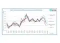
Another consideration when selecting a DC-Link capacitor is the necessary derating for temperature and voltage. Every capacitor is defined by a curve that shows the relationship between operating temperature, voltage rating, and life expectancy. As an example of DC-Link film capacitor specification see KEMET’s derating charts for the C4AQ-M and C4AK series below (Figure 1. and Figure 2.).
To obtain the same life expectancy of 100,000 h at an 85°C hotspot temperature (see the arrow in the image below), C4AQ-M requires a voltage derating of more than 10% compared to C4AK, which can operate at the same hot-spot temperature without any voltage derating required.


Therefore, a key design consideration is what operational life is needed and how that will relate to the required voltage and temperature ratings.
Other Harsh Conditions
Beyond just extreme temperatures, DC-link capacitors must be able to withstand the conditions into which they will be operating – they must be able to withstand the relative humidity, vibration, or contamination as required.
KEMET’s C4AK series capacitors are smaller and more reliable than alternatives. They boast unmatched harsh condition ratings, and because of their small size, they also have excellent vibration ratings.
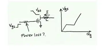
Power Dissipation
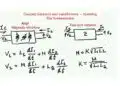
A DC-link and DC filter capacitor will experience internal heating, which will increase as the frequency of the ripple current of the semiconductors increases. The heating effect is caused by the current flowing through the internal series resistance of the capacitor. The formula used to calculate the max power dissipated by the capacitor is the following:
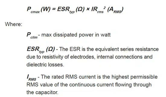
Then, the formula used to calculate the maximum power that may be dissipated by the capacitor, during thermal stability, is given by the following:
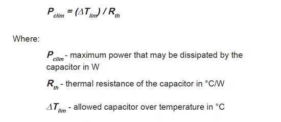
Capacitor datasheets will give the Tamb (max. ambient temperature surrounding the capacitor rating), and the graph on the following page will provide ΔTlim vs ΔTamb:
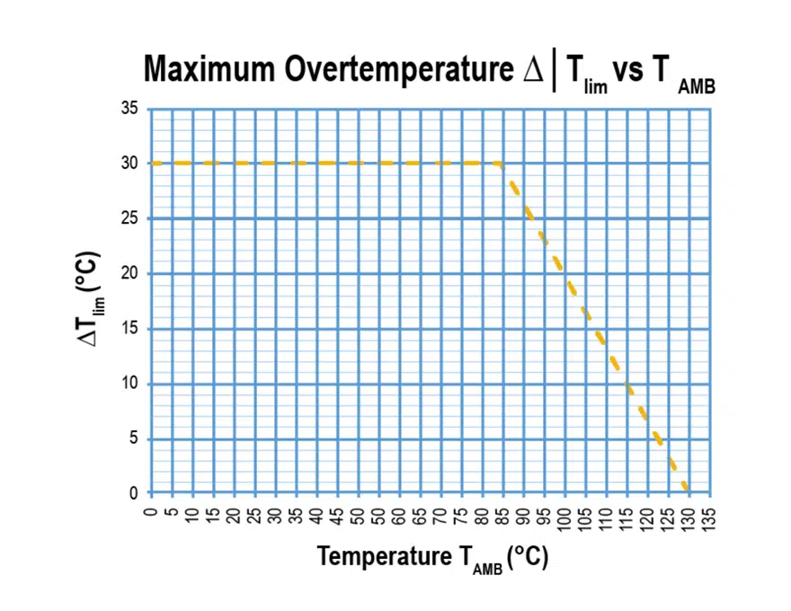
Finally, a capacitor must be selected so that the combined harmonics dissipation power in Watts does not exceed the limit conditions Pcmax < Pclim .
Selecting a DC-Link Capacitor
For our example, the requirements for the DC-Link capacitor (C3) will be given as:
- Total Cap value needed: 12 μF
- Working voltage: 420 VDC at 125°C
- Total RMS current: 10.3 A at 100°C at 10 kHz
- Application: DC-Link
- Max Ambient temperature: 125°C
Step #1: Select a Candidate Based on Capacitance and Voltage
For this example, we will select a component from the catalog of KEMET’s new C4AK metalized film power box capacitors. To do that, the first step is to select a part number from the catalog that satisfies the required capacitance value and voltage.
In this case, the selected PN is C4AKJBU5125A32J, with a capacitance of 12 μF and a voltage rating of 700 VDC.
Step #2: Find Maximum Irms Value
The next step is to find the Irms capability for this part number from the graphs provided in the datasheet at 100°C ambient temperature.
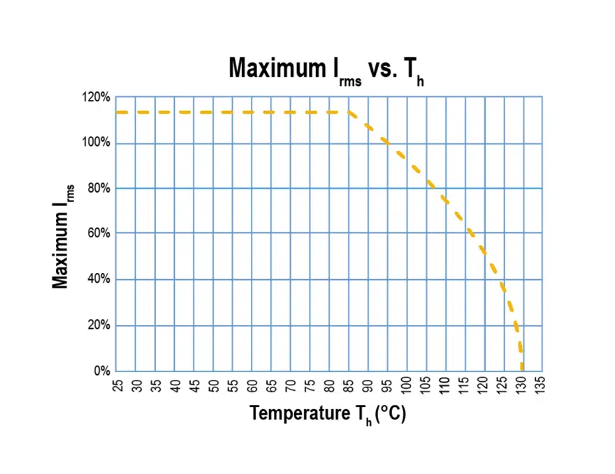
As you can see, the Irms value in the catalog corresponds to an ambient temperature of 95°C. For higher temperatures, the graph above can be used. In our application, the given requirement for the current was 10.3 A at 100°C, so the graph tells us that the maximum Irms current for this component in our application is 90% of the rated current. Referring back to the catalog or datasheet, the rated Irms at 95°C is 12.5 Arms, so in our application, the Irms maximum is 11.25 A at 100°C, which meets our requirements.
Step #3: Adjust Capacitor Selection or Quantity as Necessary
If the current rating was insufficient (meaning it was less than our required 10.3 A at 100°C) the solution would be to use more parallel capacitance capable of reaching the current requirement. But in our example, one capacitor is sufficient to meet both the capacitance and current requirements.
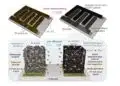
The KEMET C4AK DC-link power box capacitor in example is a metalized film capacitor in a miniaturized plastic box design that meet the demanding AEC-Q200 qualification requirements.
The most significant benefits of C4AK are:
- High capacitance density
- Good self-healing
- Low loss
- High ripple current
- Suitable harsh environmental capabilities for high-frequency applications and automotive grades (AEC-Q200) suitable for automotive applications.
- Low halogen content
The C4AK technology reaches a capacitance of up to 70 μF designed for DC-rated voltage range of 700~900 V at a maximum operating temperature of 135°C. The capacitors have remarkable temperature performance across a life expectancy of 4,000 hours at 125°C, and 1,000 hours at 135°C. This series is designed to withstand harsh environmental conditions at 85°C and 85% R.H. for 1,000 h at rated DC voltage, showing the highest humidity robustness performance.
Altogether, these characteristics and capabilities make KEMET’s C4AK metalized power box DC-Link capacitor an excellent choice for the E-charger application to increase the efficiency and performance of HEV and internal combustion engine vehicles.