


source: Planet Analog article
Reiner W. Kuehl, Senior Manager, VISHAY, 7/16/2014
Analog techniques require a certain precision of components’ electrical properties and a good prognosis of the changes that can occur during an application. This paper introduces a method for the prediction of electrical parameter changes due to aging.
The technological quality and reliability of electronic analog applications is mainly dependent on four parameters, or properties, of the electronic components in use:
- Stability of electric parameters and their characteristics, i.e. no irreversible drifts over time due to aging or degradation
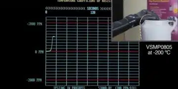
- Low and stable temperature coefficient (TC), i.e. low reversible drifts over the temperature range of the application
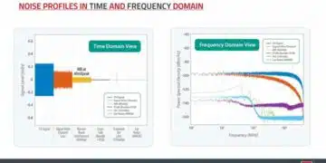
- A stable, low noise level
- A stable, low level of nonlinearity
Drifts in major electrical properties during use (e.g. the resistive value of resistors) can be a trigger for changes or drifts in other important component properties (e.g., noise, TCR, nonlinearity). High-humidity, high-temperature environmental conditions are still a challenge for many electronic components’ reliability. Their aging and degradation behaviors, as well as their acceleration factors, are not always understood well.
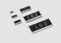
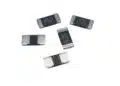
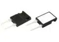
Thin film resistors are widely used in the electronics industry, and in our study, we’ve chosen them as a good general representative for the following component design: an aging or degrading functional layer on a base material protected by an organic coating. This is the basic design for many passive and active electronic components. The long-term study on the behavior of thin film resistors, in dry heat and biased humidity environments, has become the foundation for a newly developed general model covering all aging conditions in the whole temperature-humidity-time expanse, system characterization, and components’ health prognosis (lacquered or molded components having degrading functional layers).
The results were presented in 2014 at CARTS and AEC-RW and published in a peer-reviewed paper, “Influence of Bias Humidity Testing and Application on Time-Dependent, Arrhenius-Law-Based Stability Predictions for Thin Film Resistors” (subscription required).
Test program for an enhanced investigation
Our test plan considered the following points:
- Use of sensitive thin film resistor values (same batch until laser trimmed at all of the tested variants)
- Comparison of biased humidity 85°C/85% RH test results with 40°C/93% RH test
- Introduction of a new intermediate test condition at 70°C/90% RH and 90°C/40% RH
- Extended test or exposure time to 4,000 hours (10,000 hours)
- Use of two different electro-isolation lacquer variants
- Applying two voltages/loads on each variant (derived from 10% and 30% of the rated voltage)
- Comparing biased humidity results with HAST 130 (Highly Accelerated Stress Test: a biased humidity test with conditions of 130°C and 85% RH, with the same batch and electrical condition)
Results and Conclusions
It’s already common knowledge that biased humidity can be destructive to many components, depending on relative humidity and temperature. The first interesting finding of this study is that we must thoroughly differentiate between oxidation/passivation effects and corrosion mechanisms. Two different mechanisms of degradation become obvious: aging (exponentially saturated → 40°C/93% RH, 70°C/90% RH) and destructive (exponentially increasing → 85°C/85% RH) corrosion conditions.
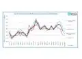
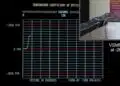
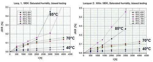 Figure 1
Test results (40°C/93% RH, 70°C/90% RH, and 85°C/85% RH).
Figure 1 shows the resulting drift characteristics after 4,000 hours of exposure time. Even at drifts as low as ΔR/R < 0.5%, the difference becomes clear. To be able to compare the different characteristics, we’ve proposed a standardization of the R-drifts to the equivalent exposure time. For example, we can estimate it as nearly nondestructive if setting this standardized drift on a low but still significant level of ΔR/R = 0.2%. With this approach, it now becomes possible to compare all biased humidity test data directly — inclusive HAST 130 results, etc.
Influencing parameter on components’ degradation/aging
We have clearly seen that temperature and humidity concentration are the driving parameters on drift or aging/degradation of the functional layer of components. Therefore, our second proposal is to use the actual present vapor pressure pvapor, instead of the relative humidity RH.
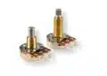
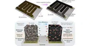
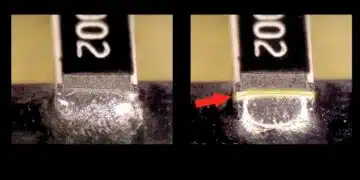
The electrical component is normally built of a core material covered by a sensitive functional metallization, which is protected by a seal, lacquer, or mold. Our thin film resistor has a base or core material of alumina, a NiCr-based R-layer, covered by an electro-isolation lacquer, as shown in Figure 2. At given environmental conditions, a pressure difference Δp exists between the lacquer-layer interface and the outside.
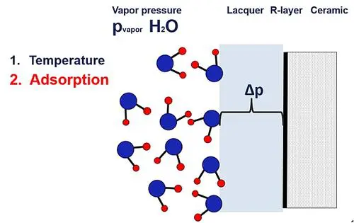 Figure 2
Vapor pressure leads to diffusion.
Equalization of pressure leads to a diffusion effect of water into the volume of the lacquer or organic coating. The concentration of water will increase in the interface area by the pressure diffusion effect. High temperatures and bias voltage in the presence of water will accelerate oxidation and cause electrochemical corrosion at the metallization. Higher temperatures will lead to a higher risk of destruction under the thermal and biased conditions.
Building the model
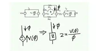
As shown in detail in the peer-reviewed paper “Influence of Bias Humidity Testing and Application on Time-Dependent, Arrhenius-Law-Based Stability Predictions for Thin Film Resistors,” water diffusion into the coating can be derived and adapted from a textbook formula. The system of pressure diffusion in electronic components can be described by one quite simple formula:
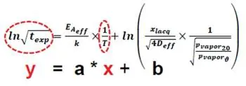
Figure 3
General formula.
This general description can be interpreted as the function of a straight line y = ax + b, where y stands for ln√ of the exposure time texp, and x for 1/T (= inverse absolute temperature T in Kelvin), as shown in Figure 3.
The factor “a” allows a direct reading and calculation of the activation energy EA of the components’ functional layer, and the constant “b” the diffusion properties of their coating (D: diffusion coefficient in µm2/h; xlacq: thickness of organic coating in µm; k: Boltzmann constant = 8.62 x 10⁻⁵ eV/K).
Since the standardized exposure time ln√texp is a direct function of inverse temperature 1/T, the components’ properties and health prognosis in the whole temperature-humidity-time expanse, as well as their system characterization, can be described and summarized in one graph: the ln√t – 1/T diagram.
Figure 4 demonstrates the capabilities of a high-ohmic-value thin film resistor with the coating “Lacquer 1” (MELF MMA0204, 180 kΩ).
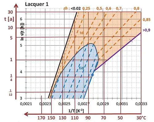 Figure 4
ln√t – 1/T diagram for a thin film resistor.
The example illustrates that an exposure time of texp > 30 years and resistive value drift of ΔR/R < 0.2 % are possible at any practical relevant relative humididy level and environmental temperatures < 100°C, without any problems for this very reliable resistor type (dependent on the activation energy of the functional thin film layer and diffusion properties of the applied coating “Lacquer 1”).
Practical application
Determining the reliability and health prognosis of electronic components becomes easy and cost effective when our ln√t – 1/T diagram is applicable.
In addition, only five reliably achieved, relevant measurement points are needed to define the drift and degradation (health prognosis) of components’ material properties (activation energy of lacquer/mold or functional layer, coefficient of diffusion, acceleration factors, etc.) over the whole relevant temperature-humidity-time expanse for all practical applications, as shown in Figure 5.
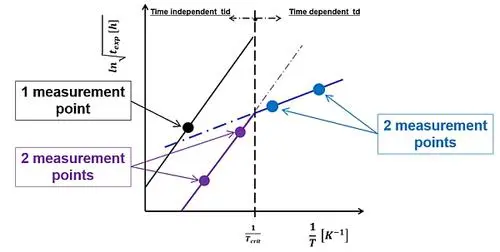 Figure 5
Five measurement points.
Highlights:
- A general (biased) humidity acceleration and long-term prognosis model is developed and defined for electronic components and investigated on sensitive thin film resistors.
- The model integrates thermal and humidity influences on degradation. Prognoses in the whole temperature-humidity-time expanse become possible.
- The defined ln√t – 1/T diagram contains all the information and enables the calculation of all relevant material data on mold/lacquer, as well as on the functional layer in question: activation energies, humidity-relevant material properties, bias voltage acceleration effects, etc.
- Differentiation between aging/oxidation and corrosion — the incoherency of these conflicting phenomena is eliminated by using standardized exposure times, instead of the measured parameter drifts.
- The (usually used) relative humidity RH can be replaced by the actual present vapor pressure as a clear physical date.
- The diffusion properties of electro-isolation lacquer or mold, respectively, have been found to be the major key for components’ parameter degradations by the impact of temperature and humidity.