


Source: Powersystems design article
Christopher Hare, Coilcraft, Inc. explains class-D audio amplifier output filter design and optimization.
Careful component selection is the key to high-quality high-efficiency Class-D audio output
When audio applications require the highest power efficiency, lowest heat generation, smallest size, and lightest weight, Class-D switched-mode amplifiers surpass the linear class amplifiers. This makes Class-D amplifiers the best choice for extending battery life in DC-powered audio applications, such as found in automotive sound systems. This article discusses how careful design of the output LC filter stage of a Class-D amplifier leads to high efficiency and high sound quality, and how choosing the right inductor affects these critical parameters.
Efficiency and Sound Quality Considerations
Linear amplifiers have very low theoretical limits on power efficiency. While distortion for Class-A amplifiers is low, the ideal upper limit for Class-A efficiency is only 50%. The high resistance of the output stage transistors results in dissipation that generates significant heat, typically requiring large heatsinks to keep the design at an acceptable temperature. This wastes energy and adds weight to the overall design. Class B amplifiers dissipate less power, but have inferior sound quality due to non-linear crossover distortion of the push-pull controller transitioning between on and off conditions.
Class-AB is a compromise between Class-A and -B characteristics. It has less dissipation than Class-A, eliminating crossover distortion and giving good sound quality. However, Class-AB still has significant dissipation and an upper theoretical limit on efficiency lower than the Class-B limit of 78%. This can be a major disadvantage for DC-powered audio systems, especially at high power levels.
The theoretical efficiency limit of Class-D amplifiers is 100%. While this cannot be achieved in practice due to the uncompromising second law of thermodynamics, the efficiency of Class-D amplifiers is significantly higher than the linear amplifier classes, achieving over 90% at full load. With proper design, sound quality can be comparable to Class-AB.
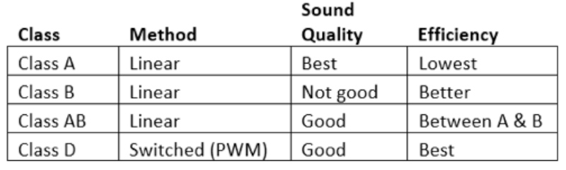
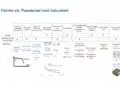
Figure 1: Comparison of Amplifier Class Attributes
Basic Operation of Class-D
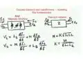
Now that we have chosen Class-D for our audio amplifier design, let’s outline the operation of Class-D amplifiers. The basic Class-D block diagram is shown in Figure 2. In the first stage, the low-voltage audio input is compared to a triangular waveform to generate a train of fixed-amplitude square pulses. Next, the pulse-width-modulated (PWM) pulses are fed to the switching controller and output stage, which functions similarly to a backward synchronous buck converter. The most common configuration for the output stage is bridge-tied load (BTL) which has 2x more voltage swing across the load compared to single-ended and 4x the output power. The result is a higher-frequency, higher-voltage square wave being fed to the load, typically a 4 Ohm or 8 Ohm speaker.
Before the square wave is fed to the speaker, it must pass through a low-pass LC filter in order to remove the high-frequency switching content and pass only the audio frequency range (typically 20 Hz to 20 kHz) to the speaker. The LC filter also limits the residual ripple current at idle conditions, which improves efficiency.
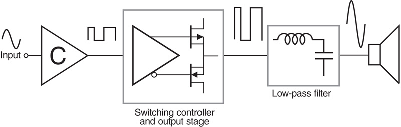
Figure 2: Class-D Amplifier Diagram Source: https://en.wikipedia.org/wiki/Class-D_amplifier
The switching frequency of the Class-D amplifier determines the filter order and cutoff frequency requirements. Higher switching frequencies allow for smaller components and lower order filters to achieve the required attenuation in the stop band, but this may cause higher EMI and switching losses. In most Class-D audio applications, the switching frequency is in the range of 200 kHz to 2 MHz.
Low-pass LC Filter Design
For very cost-sensitive or smaller form factor requirements, filterless solutions may be feasible, but these can lead to EMI problems and high-frequency power dissipation due to the switching waveforms. A filterless design is not practical in a “noisy” automotive environment. As with all things engineering, there are trade-offs in performance vs. size and cost of the LC filter components. Using proven Class-D reference designs and evaluation modules as a starting point can help reduce the time needed to design and test an optimal solution, however, there certainly are interesting challenges in designing Class-D LC filters. Understanding the requirements can provide insights into any trade-offs that may need to be made.
The output LC filter is a critical element in determining the size, sound quality, and efficiency of a Class-D sound system. The output filter is designed to attenuate the high frequency switching component while passing the audio frequency band of 20 Hz to 20 kHz. One low-pass LC filter is needed for each audio channel. Keeping the component count to a minimum helps reduce the total required real estate.
The typical Class-D LC filter implementation is a second-order Butterworth LC filter, which creates a flat pass-band and phase response with a small number of components. A second order filter gives -40 dB per decade. Selection of the LC values requires an understanding of the speaker load impedance variation for the application. The ideal L and C values result in a critically-damped response with a flat passband and flat phase response. An overdamped response attenuates the audio content, and an underdamped response leads to peaks that may trigger built-in circuit protection or harsh sound.
Class-D BTL filters are defined by three types: Type-1, Type-2, or hybrid. The type defines a differential (Type-1), common mode (Type-2), or hybrid filter implementation that depends on the pulse width modulation (PWM) scheme (AD or BD). Type-1 filters with traditional AD modulation are the simplest and will be used in the following example.
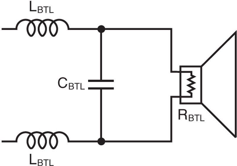
Figure 3: Class-D Type-1 Differential Bridge Tied Load (BTL) CircuitLBTL = Series inductance
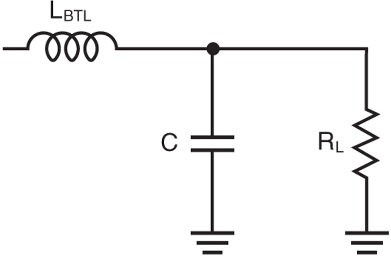
Figure 4: Class-D Type-1 Single-Ended Equivalent Circuit
LBTL = Series inductance
CBTL = Differential bridge tied load capacitor
RBTL= Differential (speaker) load
RL = Single-ended equivalent load = RBTL / 2
C = Single-ended capacitor tied to ground = 2 x CBTL
The L and C values for a critically damped Butterworth filter are:
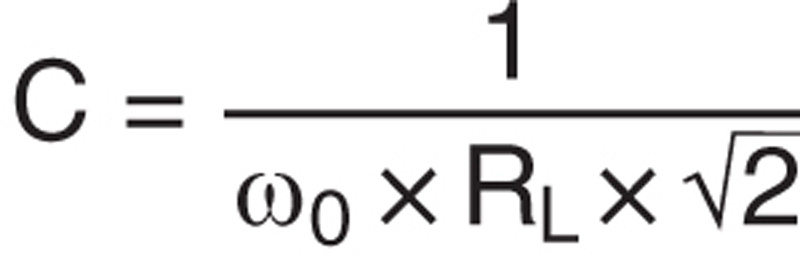
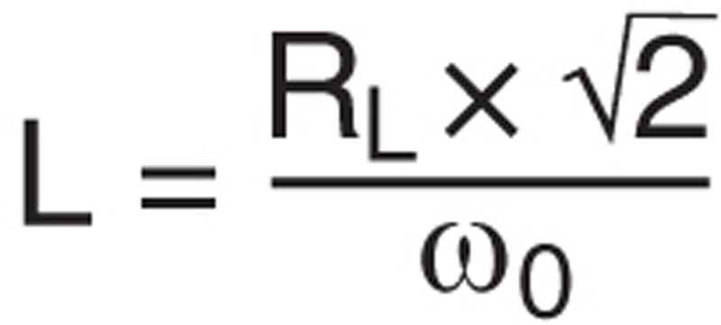
where ω0 is 2 x π x f0
For a cutoff frequency (f0) of 40 kHz and a 4 Ohm speaker load:
C = 1.4 μF and CBTL = C/2 = 0.70 μF
The nearest standard capacitance value is 0.68 μF
L = 11.25 μH.
The nearest standard inductor value is 10 μH.
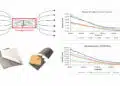
Once the L and C values are selected, graphing the gain vs frequency over the expected range of speaker impedance, typically in the 2-8 Ohm range, allows the designer to determine whether the performance is acceptable for that range.
Consult the LC Filter Design reference below for a more detailed discussion of the Type-2 and hybrid filter implementations and capacitor selection. For Type-2, the only difference for the single-ended analysis is that Cg = C compared to CBTL = C/2 for Type 1. For the hybrid type, adding caps Cg to ground (Cg ~ 1/10th of CBTL) improves the filtering by coupling high frequencies to ground.
Inductor Selection
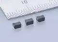
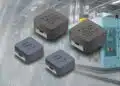
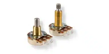
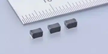
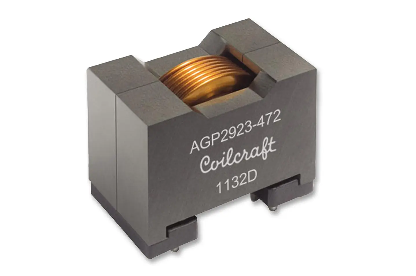
For the 4 Ohm to 8 Ohm speaker range, typical LBTL values range from about 5 to 20 μH, and a selection of off-the-shelf inductors in this range are available for Class-D applications for various power requirements. Selecting an inductor that does not vary significantly with current is important in maintaining linearity and minimizing distortion and noise. Higher current requirements typically necessitate a larger inductor size to minimize distortion. Having two uncoupled inductors in a single package minimizes the LC filter footprint, saving critical board space in space-constrained applications such as automotive Class-D audio systems.
The objective measurement that defines sound quality is total harmonic distortion and noise (THD + N). Low THD + N is crucial in the typical hearing-sensitive 1 kHz to 6 kHz frequency range. The optimal inductor choice involves trade-offs in peak current handling, core and winding losses at operating conditions, and part size. Inductor manufacturers have designed single and dual off-the shelf inductors specifically tailored for Class-D audio applications. These inductors balance the requirements for both high-quality sound and high efficiency.
featured image credit: Coilcraft