Passive Components Blog
No Result
View All Result
  • Home
  • NewsFilter
    • All
    • Aerospace & Defence
    • Antenna
    • Applications
    • Automotive
    • Capacitors
    • Circuit Protection Devices
    • electro-mechanical news
    • Filters
    • Fuses
    • Inductors
    • Industrial
    • Integrated Passives
    • inter-connect news
    • Market & Supply Chain
    • Market Insights
    • Medical
    • Modelling and Simulation
    • New Materials & Supply
    • New Technologies
    • Non-linear Passives
    • Oscillators
    • Passive Sensors News
    • Resistors
    • RF & Microwave
    • Telecommunication
    • Weekly Digest

    Nichicon Extends Rechargeable Batteries Temperature to Rival Supercapacitors

    Two‑capacitor paradox explained for engineers

    YAGEO Releases Compact RJ45 Connector for Multi‑Gigabit Ethernet

    Circuit Protection Technology Annual Dossier

    ESA SPCD 26 Registration Open

    Capacitances of Nonlinear MLCCs: What Datasheets Don’t Tell You

    Stackpole Releases Automotive Wide‑Termination Resistors

    How a Digital Structural Twin Can Predict Tantalum Capacitor Reliability

    SCHURTER Buys Biaodi to Boost High-Voltage Protection Portfolio

    Trending Tags

    • Ripple Current
    • RF
    • Leakage Current
    • Tantalum vs Ceramic
    • Snubber
    • Low ESR
    • Feedthrough
    • Derating
    • Dielectric Constant
    • New Products
    • Market Reports
  • VideoFilter
    • All
    • Antenna videos
    • Capacitor videos
    • Circuit Protection Video
    • Filter videos
    • Fuse videos
    • Inductor videos
    • Inter-Connect Video
    • Non-linear passives videos
    • Oscillator videos
    • Passive sensors videos
    • Resistor videos

    Two‑capacitor paradox explained for engineers

    Capacitances of Nonlinear MLCCs: What Datasheets Don’t Tell You

    Tapped Inductor Buck Converter Fundamentals

    Planar vs Conventional Transformer: When it Make Sense

    Modeling Fringing Field Losses in Inductors & Transformers

    Why Power Inductors Use a Ferrite Core With an Air Gap

    Transformer-Based Power-Line Harvester Magnetic Design

    Thermal Modeling of Magnetics

    Standard vs Planar LLC transformers Comparison for Battery Chargers

    Trending Tags

    • Capacitors explained
    • Inductors explained
    • Resistors explained
    • Filters explained
    • Application Video Guidelines
    • EMC
    • New Products
    • Ripple Current
    • Simulation
    • Tantalum vs Ceramic
  • Knowledge Blog
  • DossiersNew
  • Suppliers
    • Who is Who
  • PCNS
    • PCNS 2025
    • PCNS 2023
    • PCNS 2021
    • PCNS 2019
    • PCNS 2017
  • Events
No Result
View All Result
Passive Components Blog
No Result
View All Result

Physical Transformer Modelling in LTSpice

10.10.2023
Reading Time: 7 mins read
A A

Sotiris Zorbas, Power Εlectronics Εngineer of Frenetic in this blog explains how to build a transformer model in LTspice or Suzuka from measurements of a physical transformer.

The Transformer Model

RelatedPosts

Planar vs Conventional Transformer: When it Make Sense

Modeling Fringing Field Losses in Inductors & Transformers

Modeling Planar Magnetics Temperature: Practical Guidelines for Power Electronics Engineers

In Figure 1, if we omit the capacitors Cp, Cs we have a power source, a Transformer model, and a load resistor. Adding the series capacitor, we have the trending CLLC topology that is currently trending in the automotive world.

Figure 1. Transformer model for a SS WPT system identical to CLLC converter

Can you believe I took this picture 7 years ago, when I was writing my thesis for the development of a complete wireless power system (WPT)? The industry back then hadn’t made the decision to move electric just yet (“thanks, Elon”). Back then, wireless power transfer was a trending topic with multiple new papers published across the globe. Mainly, the goal of the research groups was to explain the various modes of operation of WPT systems.

Figure 1 depicts the SS WPT topology because the capacitors are connected in series with Transformer. The only major difference between an SS WPT system and a CLLC Converter is the coupling factor k, not considering operation modes. You see in a WPT system, the inductors are facing each other and behave like a loosely coupled transformer.

Useful definitions and the connection to measurements

First of all:

  • LP is the primary inductance.
  • LM is the magnetizing inductance.
  • Llkp is the primary leakage inductance.

When we build an inductor and choose x turns, given the AL value of the material, we get the inductance L=x2AL.  If that is the primary winding of a Transformer, we call this inductance, primary inductance LP . Now, if the Transformer was an ideal one, then the coupling factor is equal to 1, and there are zero leakage inductances.

In the case of a real Transformer, as modelled in Figure 1, the primary “isn’t coupled” to the secondary completely, so LP is split between the leakage and the magnetizing inductance, depending on the coupling factor. The magnetizing inductance is the largest percentage of the primary inductance, responsible for power transfer, whilst the rest acts like an inductor storing energy in series.

As said:

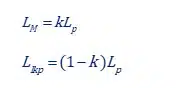
Usually, the coupling factor k has values like 0.999, so almost all primary inductance is magnetizing inductance with a tiny percentage of it is left as leakage inductance Llkp. But in a WPT application, or in a resonant topology like LLC or CLLC, the coupling factor can take much lower values.

Also:

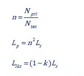
  • Turns ratio n is known
  • LP  is known from the AL value and turns and can be easily measured if we just measure the primary inductance with all other windings open
  • The coupling k factor is not known. If we know k, then we can calculate the primary and secondary leakage inductances and the Transformer model of Figure 1 is complete!

Do you know how to measure the k factor?

If your answer is “what do I need the k factor for, I just short the secondary and measure the leakage in the primary, which I call primary leakage”, then you’re right only if you assume the k factor is very close to unity.

When however, you design resonant Transformers you are about to commit mistakes thinking that way! Let’s look at what exactly happens if we short the secondary winding and measure from the primary side:

Figure 2. Shorting the secondary and measuring inductance at the primary side

As seen in Figure 2, we don’t measure the primary leakage, but more correctly the “lumped”/ “effective”/ “total” leakage of the transformer that way. Well, that leakage is close to the primary leakage if we assume that the secondary leakage inductance is much lower than the magnetizing inductance, thus the parallel combo value is close to zero. You see the fault in these assumptions…

Instead of assumptions, we can write the following for the equation:

So, the total inductance which I like to call Lshort is:

And after a page long of equation manipulations:

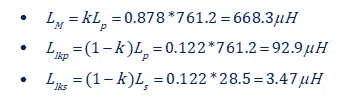
Now you can easily calculate k with this easy measurement and define all leakage inductances exactly. An example:

Figure 3. Example LLC Transformer simulation and measured values

Calculating the k factor (in an LLC- center tap the short test is done with one of the 2 secondaries):

So:

One key skill is connecting theory and practice, with knowledge about parasitic elements and assumptions made in the process, no matter of the subject.

Related

Source: Frenetic

Recent Posts

Two‑capacitor paradox explained for engineers

18.5.2026
29

ESA SPCD 26 Registration Open

15.5.2026
23

Capacitances of Nonlinear MLCCs: What Datasheets Don’t Tell You

14.5.2026
79

How a Digital Structural Twin Can Predict Tantalum Capacitor Reliability

14.5.2026
56

Tapped Inductor Buck Converter Fundamentals

13.5.2026
38

TAIYO YUDEN Releases Mini Metal Power Inductors

13.5.2026
48

Molecular Memristor Shows Record 145 kH Emergent Inductance

12.5.2026
44

Planar vs Conventional Transformer: When it Make Sense

11.5.2026
82

High-Crystallinity Nanocrystalline Composites for MHz Chip Inductors

7.5.2026
69

Upcoming Events

May 19
16:00 - 17:00 CEST

Designing Qi2 Wireless Power Systems: Practical Development and EMC Optimization

Jun 2
16:00 - 17:00 CEST

Calculation, Simulation and Measurement of 800V EMC Filters

Jun 16
16:00 - 17:00 CEST

EMC with EMC – EMC‑compliant design with electromechanical connectors

View Calendar

Popular Posts

  • Buck Converter Design and Calculation

    0 shares
    Share 0 Tweet 0
  • Boost Converter Design and Calculation

    0 shares
    Share 0 Tweet 0
  • Flyback Converter Design and Calculation

    0 shares
    Share 0 Tweet 0
  • LLC Resonant Converter Design and Calculation

    0 shares
    Share 0 Tweet 0
  • MLCC and Ceramic Capacitors

    0 shares
    Share 0 Tweet 0
  • Capacitor Charging and Discharging

    0 shares
    Share 0 Tweet 0
  • What Electronics Engineer Needs to Know About Passive Low Pass Filters

    0 shares
    Share 0 Tweet 0
  • Dual Active Bridge (DAB) Topology

    0 shares
    Share 0 Tweet 0
  • Ripple Current and its Effects on the Performance of Capacitors

    3 shares
    Share 3 Tweet 0
  • MLCC Case Sizes Standards Explained

    0 shares
    Share 0 Tweet 0

Newsletter Subscription


Passive Components Blog

© EPCI - Leading Passive Components Educational and Information Site

  • Home
  • Privacy Policy
  • EPCI Membership & Advertisement
  • About

No Result
View All Result
  • Home
  • Knowledge Blog
  • PCNS

© EPCI - Leading Passive Components Educational and Information Site

This website uses cookies. By continuing to use this website you are giving consent to cookies being used. Visit our Privacy and Cookie Policy.
Go to mobile version