Passive Components Blog
No Result
View All Result
  • Home
  • NewsFilter
    • All
    • Aerospace & Defence
    • Antenna
    • Applications
    • Automotive
    • Capacitors
    • Circuit Protection Devices
    • electro-mechanical news
    • Filters
    • Fuses
    • Inductors
    • Industrial
    • Integrated Passives
    • inter-connect news
    • Market & Supply Chain
    • Market Insights
    • Medical
    • Modelling and Simulation
    • New Materials & Supply
    • New Technologies
    • Non-linear Passives
    • Oscillators
    • Passive Sensors News
    • Resistors
    • RF & Microwave
    • Telecommunication
    • Weekly Digest

    LeanBOM: Practical Cross‑Technology Capacitor Search by Real Working Conditions

    In the Age of AI, Every Watt Counts: Implications for Components

    Stackpole Extends Resistance Range of 2512 High‑Power Current Sense Resistors

    Wk 27 Electronics Supply Chain Digest

    Littelfuse Announced TVS Diodes for 48 V Automotive Systems

    Spectrum Controls Joins Modelithics Program to Offer High‑Fidelity RF Models for Resistors, Attenuators and Terminations

    RF Filters and Passive Components Enabling the 7 Missile RF Subsystems

    Ferrite versus Nanocrystalline Power Inductor Cores: Turns, Gap and Size

    YAGEO Presents NANOMET Soft Magnetic Cores for High‑Density Power Conversion

    Trending Tags

    • Ripple Current
    • RF
    • Leakage Current
    • Tantalum vs Ceramic
    • Snubber
    • Low ESR
    • Feedthrough
    • Derating
    • Dielectric Constant
    • New Products
    • Market Reports
  • VideoFilter
    • All
    • Antenna videos
    • Capacitor videos
    • Circuit Protection Video
    • Filter videos
    • Fuse videos
    • Inductor videos
    • Inter-Connect Video
    • Non-linear passives videos
    • Oscillator videos
    • Passive sensors videos
    • Resistor videos

    Ferrite versus Nanocrystalline Power Inductor Cores: Turns, Gap and Size

    KYOCERA AVX Presents Antenna Integrator Studio Tutorial for Antenna Placement and RF Design

    Power Design Simulation Tools for Faster Inductor Selection and Loss Optimization

    EMC‑Compliant PCB and Connector Design Guidelines

    Why Isolated DC/DC Power Supplies Fail Late, Würth Elektronik Podcast

    Designing 800 V DC EMC Filters: Calculation, Simulation and Measurement

    Current Sense Transformer Datasheet and Design‑in Guide

    Designing a USB Type‑C Flyback Planar Transformer with Frenetic’s Planar Tool

    Magnetics Design in High‑Frequency GaN Converters

    Trending Tags

    • Capacitors explained
    • Inductors explained
    • Resistors explained
    • Filters explained
    • Application Video Guidelines
    • EMC
    • New Products
    • Ripple Current
    • Simulation
    • Tantalum vs Ceramic
  • Knowledge Blog
  • Dossiers
    • AI Hardware Dossier
    • Power Converter Dossier
    • Automotive Dossier
    • Capacitor Dossier
    • Resistor Dossier
    • Inductor Dossier
    • Circuit Protection Dossier
  • Suppliers
    • Who is Who
  • PCNS
    • PCNS 2025
    • PCNS 2023
    • PCNS 2021
    • PCNS 2019
    • PCNS 2017
  • Events
  • Home
  • NewsFilter
    • All
    • Aerospace & Defence
    • Antenna
    • Applications
    • Automotive
    • Capacitors
    • Circuit Protection Devices
    • electro-mechanical news
    • Filters
    • Fuses
    • Inductors
    • Industrial
    • Integrated Passives
    • inter-connect news
    • Market & Supply Chain
    • Market Insights
    • Medical
    • Modelling and Simulation
    • New Materials & Supply
    • New Technologies
    • Non-linear Passives
    • Oscillators
    • Passive Sensors News
    • Resistors
    • RF & Microwave
    • Telecommunication
    • Weekly Digest

    LeanBOM: Practical Cross‑Technology Capacitor Search by Real Working Conditions

    In the Age of AI, Every Watt Counts: Implications for Components

    Stackpole Extends Resistance Range of 2512 High‑Power Current Sense Resistors

    Wk 27 Electronics Supply Chain Digest

    Littelfuse Announced TVS Diodes for 48 V Automotive Systems

    Spectrum Controls Joins Modelithics Program to Offer High‑Fidelity RF Models for Resistors, Attenuators and Terminations

    RF Filters and Passive Components Enabling the 7 Missile RF Subsystems

    Ferrite versus Nanocrystalline Power Inductor Cores: Turns, Gap and Size

    YAGEO Presents NANOMET Soft Magnetic Cores for High‑Density Power Conversion

    Trending Tags

    • Ripple Current
    • RF
    • Leakage Current
    • Tantalum vs Ceramic
    • Snubber
    • Low ESR
    • Feedthrough
    • Derating
    • Dielectric Constant
    • New Products
    • Market Reports
  • VideoFilter
    • All
    • Antenna videos
    • Capacitor videos
    • Circuit Protection Video
    • Filter videos
    • Fuse videos
    • Inductor videos
    • Inter-Connect Video
    • Non-linear passives videos
    • Oscillator videos
    • Passive sensors videos
    • Resistor videos

    Ferrite versus Nanocrystalline Power Inductor Cores: Turns, Gap and Size

    KYOCERA AVX Presents Antenna Integrator Studio Tutorial for Antenna Placement and RF Design

    Power Design Simulation Tools for Faster Inductor Selection and Loss Optimization

    EMC‑Compliant PCB and Connector Design Guidelines

    Why Isolated DC/DC Power Supplies Fail Late, Würth Elektronik Podcast

    Designing 800 V DC EMC Filters: Calculation, Simulation and Measurement

    Current Sense Transformer Datasheet and Design‑in Guide

    Designing a USB Type‑C Flyback Planar Transformer with Frenetic’s Planar Tool

    Magnetics Design in High‑Frequency GaN Converters

    Trending Tags

    • Capacitors explained
    • Inductors explained
    • Resistors explained
    • Filters explained
    • Application Video Guidelines
    • EMC
    • New Products
    • Ripple Current
    • Simulation
    • Tantalum vs Ceramic
  • Knowledge Blog
  • Dossiers
    • AI Hardware Dossier
    • Power Converter Dossier
    • Automotive Dossier
    • Capacitor Dossier
    • Resistor Dossier
    • Inductor Dossier
    • Circuit Protection Dossier
  • Suppliers
    • Who is Who
  • PCNS
    • PCNS 2025
    • PCNS 2023
    • PCNS 2021
    • PCNS 2019
    • PCNS 2017
  • Events
No Result
View All Result
Passive Components Blog
No Result
View All Result

A Simple Method for a Capacitor’s ESR Measurement

27.11.2019
Reading Time: 6 mins read
A A

source: Power Electronics article

Farzin Asadi, Nurettin Abut | Sep 07, 2017, Accurate modeling of power electronic converters, i.e., obtaining control to output transfer function, must include series resistance of capacitors and inductors. A simple method allows measurement of a capacitor’s Equivalent Series Resistance (ESR).

RelatedPosts

KEMET Design it Day: Capacitors and Inductors Selection Guide for Decoupling And Filtering

How to determine and measure MLCC ripple current and ESR

Degradation of ESR in Polymer Tantalum Capacitors during High Temperature Storage BEST PAPER AWARD

 Capacitors are classified according to their dielectric’s type. Electrolytic capacitors are popular in power electronic circuits, due to their high volumetric efficiency and excellent price performance ratio.[1] Unfortunately, their characteristics change with operating frequency, whereas an ideal capacitor’s impedance decreases with frequency. But, in the real world this is not seen in the laboratory. Increasing frequency up to a certain point leads to the expected impedance reduction but increasing frequency causes the impedance to increase, i.e., it acts like a resonance circuit. To model the behavior of an actual capacitor requires the addition of extra elements to the capacitor model. ESR is actually the resistance that a capacitor shows in the border between capacitor-like behavior and inductor-like behavior, i.e., resistance at the resonance frequency.

When modeling the dynamic behavior of power converters, ESR is important value because it predicts the output ripple of the converter as well as predicting capacitor lifetime.[2] Power dissipated in ESR causes the capacitor’s temperature to increase and its capacitance and lifetime to decrease.

A simple and direct method for measuring ESR is proposed in [3], in which the ESR is determined directly by the ratio of the capacitor’s ripple voltage to ripple current. But the implementation is quite expensive and troublesome. To determine ESR using only voltage measurements, Chen et al. [4] suggested that under some specific conditions, the inductor ripple current could be assumed to be constant and hence the output ripple voltage determines the ESR. However, the proposed method is limited and its precision is not high.

 A laboratory method that can be used to determine the intrinsic value of ESR of electrolytic capacitors was proposed in [5]. However, the method is expensive to implement.

Here, we present a simple measurement technique for the determination of capacitor ESR.

Proposed Method:

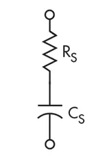
Assume a model like that shown in Fig. 1, for Capacitor Under Test (CUT):

1. Model of capacitor under test.


This model ignores lead inductance. Suppose that CUT is connected to a sine wave generator with frequency Fg and internal resistance rg, as shown in Fig. 2:

2. CUT connected to a sine wave generator.

The transfer function of this circuit is:

Equation 1, shows the high pass nature of this circuit. Therefore, we can approximate the transfer function as:

Equation 2 is the basis for our capacitor ESR measurement. When the input frequency is high enough we can simplify the input-output relation as algebraic Equation 2. For high frequencies, the circuit acts like an attenuator with the attenuation factor:

Measurement of circuit’s attenuation factor and generator’s internal resistance leads to rc, the capacitor’s ESR:

Instead of using a sine wave excitation, we can use a square wave. This allows us to use a Fourier series to write an equation with levels +Vm and -Vm, and period T:

Where:

A square wave consists of odd harmonics. When fundamental harmonic is high enough, a capacitor acts like short circuit and output voltage is approximately attenuated version of input voltage in steady state. Circuit attenuation in steady state is directly related to capacitor equivalent series resistance, rc , that can be obtained by measuring the circuit’s attenuation factor and using Equation 3.

Simulation Results:

Simulink diagram is shown in Fig. 3:

3. Simulation diagram of circuit in Simulink.

A square wave with amplitude +1 and -1 volt is used as excitation. Signal generator output resistance is taken as 50 Ω, capacitor is 30 μF with 0.8 Ω ESR. Steady-state output waveform is shown in Fig. 4:


4. Steady-state output of circuit.

The calculated attenuation factor of the circuit is:

and CUT’s ESR is calculated as:

Laboratory Results:

A signal generator with nominal 50 Ω output resistance provides the excitation. An output resistance of 47.1 Ω is measured with the aid of a simple voltage divider. Steady state output voltage peak-peak voltage is measured with the aid of a digital scope. Figure 5 shows s sample output.

5. Sample output voltage waveform.

Calculated ESR Values

This simple measurement technique provides accurate results and allows a more precise power converter model.


References

1. Amaral A.M.R., Cardoso A.J.M.: An experimental technique for estimating the ESR and reactance intrinsic values of aluminium electrolytic capacitors. Proc. Instrumentation and Measurement Technology Conf., IMTC 2006, April 2006, pp. 1820–1825.


2. Sankaran V.A., Rees F.L., Avant C.S.: Electrolytic capacitor life testing and prediction. Proc. 32nd Annual Meeting IEEE Industry Applications Society, October 1997, vol. 2, pp. 1058–1065

3. Venet P., Perisse F., El-Husseini M.H., Rojat G.: Realization of a smart electrolytic capacitor circuit, IEEE Ind. Appl. Mag., 2002, 8, (1), pp. 16–20

4. Chen Y.-M., Chou M.-W., Wu H.-C.: Electrolytic capacitor failure prediction of LC filter for switching-mode power converters. Proc. 40th Annual Meeting IEEE Industry Applications Society, October 2005, vol. 2, pp. 1464–1469.

5. Amaral A.M.R., Cardoso A.J.M.: An ESR meter for high frequencies. Proc. Int. Conf. on Power Electronics and Drives Systems, PEDS, 2005, pp. 1628–163

6. D.W. Hart, “Power electronics,” Mc Graw Hill, 2010.

7. N. Mohan,T. M. Undeland , W. P. Robbins, “Power Electronics: Converters, Applications and Design,” John Wiley and Sons, 2002.

8. R.W. Ericson, D. Maksimovic, “Fundamental of power electronics,” Springer, 2001.

9. A.M.R. Amaral, A.J.M Cardoso: “An ESR meter for high frequencies“. Proc. Int. Conf. on Power Electronics and Drives Systems, PEDS, 2005, pp. 1628–1633.

10. R. Chen, J.D.V. Wyk, S. Wang, W.G. Odendaal: Improving the characteristics of integrated EMI filters by embedded conductive layers. IEEE Trans. Power Electron., 2005, pp. 611–619.

11. A.M.R. Amaral, A.J.M Cardoso: An experimental technique for estimating the ESR and reactance intrinsic values of aluminium electrolytic capacitors. Proc. Instrumentation and Measurement Technology Conf., IMTC 2006, April 2006, pp. 1820–1825.

Related

Recent Posts

LeanBOM: Practical Cross‑Technology Capacitor Search by Real Working Conditions

13.7.2026
19

In the Age of AI, Every Watt Counts: Implications for Components

13.7.2026
17

RF Filters and Passive Components Enabling the 7 Missile RF Subsystems

9.7.2026
44

From DCL to SSC: Bridging Electrical Symptoms and Structural Indicators in Tantalum Capacitors

7.7.2026
57

High-Q RF & Microwave MLCCs: A Cross-Vendor Benchmark

2.7.2026
81

TAIYO YUDEN Introduced Hybrid Aluminum Capacitors for 48V Automotive Power Supplies

2.7.2026
74

YAGEO Announces July 2026 Capacitor Price Increase

1.7.2026
735

Enabling the 800 V AI Server Era: How C0G High-Voltage MLCC Supports Next-Generation Power Architectures

1.7.2026
161

MLCCs in the Age of AI: Q2 2026 Market Tightness

30.6.2026
461

Upcoming Events

Jul 14
16:00 - 17:00 CEST

EMC Design Essentials: Mastering Varistors and Common Mode Chokes

Jul 21
16:00 - 17:00 CEST

Safety by design: X and Y Interference suppression capacitors for power line filters

Jul 28
8:00 - 11:00 CEST

Post Procurement Testing of EEE Components for LEO Space Applications

View Calendar

Popular Posts

  • Boost Converter Design and Calculation

    0 shares
    Share 0 Tweet 0
  • Buck Converter Design and Calculation

    0 shares
    Share 0 Tweet 0
  • Flyback Converter Design and Calculation

    0 shares
    Share 0 Tweet 0
  • LLC Resonant Converter Design and Calculation

    0 shares
    Share 0 Tweet 0
  • YAGEO Announces July 2026 Capacitor Price Increase

    0 shares
    Share 0 Tweet 0
  • MLCC and Ceramic Capacitors

    0 shares
    Share 0 Tweet 0
  • Earthing Systems and IEC Classification Explained

    0 shares
    Share 0 Tweet 0
  • Nvidia Vera Rubin: Why One AI Rack Needs So Many More MLCC Capacitors

    0 shares
    Share 0 Tweet 0
  • MLCCs in the Age of AI: Q2 2026 Market Tightness

    0 shares
    Share 0 Tweet 0
  • Dual Active Bridge (DAB) Topology

    0 shares
    Share 0 Tweet 0

Newsletter Subscription


Passive Components Blog

© EPCI - Leading Passive Components Educational and Information Site

  • Home
  • Privacy Policy
  • EPCI Membership & Advertisement
  • About

No Result
View All Result
  • Home
  • Knowledge Blog
  • Dossiers
  • PCNS

© EPCI - Leading Passive Components Educational and Information Site

This website uses cookies. By continuing to use this website you are giving consent to cookies being used. Visit our Privacy and Cookie Policy.
Go to mobile version