


This article describes aluminum electrolytic capacitors types, features, characteristics and behaviour.
The primary strength of aluminum electrolytic capacitors is their ability to provide a large capacitance value in a small package, and do so for a relatively low cost.
Additionally, they tend to have good self-healing characteristics; when a localized weak spot in the aluminum oxide dielectric layer develops, the increased leakage current flow through the weak point in the dielectric causes a chemical reaction similar to that used during the initial formation of the dielectric layer, resulting in a thickening of the dielectric at the weak point, and a consequent reduction in leakage current.
Construction, Features and Manufacturing Process of Aluminum Capacitors
The shortcomings of aluminum capacitors are mostly related to
- the chemically-reactive nature of the materials used in their construction
- the conductive properties of the electrolyte solutions
- the volatility of liquid electrolytes.
The chemically reactive nature of the materials used in aluminum capacitors is problematic on two points; the stability of the dielectric layer and the long-term mechanical integrity of the device.
Since the aluminum oxide dielectric layer in these devices is formed through an electrochemical process, it can also be eroded by an electrochemical process simply by reversing the applied voltage. This is why most aluminum capacitors are polarized; application of voltage with the wrong polarity causes rapid erosion & thinning of the dielectric, resulting in high leakage current and excessive internal heating.
From a mechanical integrity standpoint, mixing a highly reactive metal (aluminum) with a corrosive electrolyte solution is a delicate proposition; errors in electrolyte composition can result in premature failure, as evidenced by the “capacitor plague” of the early 2000’s.
Another shortcoming of aluminum electrolytic capacitors is the fact that the electrolytes used aren’t particularly efficient conductors, because conduction in electrolyte solutions is achieved through ionic, rather than electronic conduction; instead of loose electrons moving between atoms serving as the charge carriers, ions (atoms or small groups thereof that have a charge due to a surplus or deficit of electrons) are moving about through the solution. Since ions are more bulky than electrons, they don’t move as easily and hence ionic conduction generally tends to be a higher-resistance proposition than electronic conduction. The extent to which this is the case is influenced significantly by temperature; the lower the temperature, the more difficult it is for ions in an electrolyte solution to move about through the solution, which translates into a higher resistance. Thus, electrolytic capacitors tend to have a relatively high ESR that exhibits a strong inverse correlation with temperature.
The third major downside to aluminum capacitors (with the exception of the solid polymer types) is that the liquid electrolyte solutions tend to evaporate over time, eventually being lost to the atmosphere by diffusion through the rubber sealing plug, leaks in safety vent structures, or similar phenomena.
There are more types of aluminum electrolytic capacitors construction and termination styles:
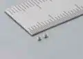
- SMDs (V-chip) for surface mounting on printed circuit boards or substrates
- Radial lead terminals (single ended) for vertical mounting on printed circuit boards
- Axial lead terminals for horizontal through hole mounting on printed circuit boards
- Radial pin terminals (snap-in) for power applications
- Press-fit terminals
- Large screw terminals for power applications
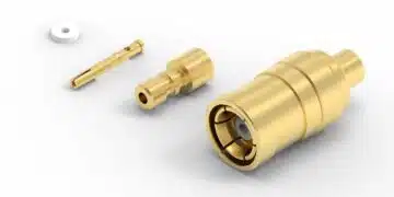
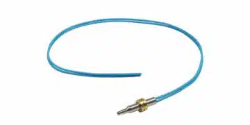
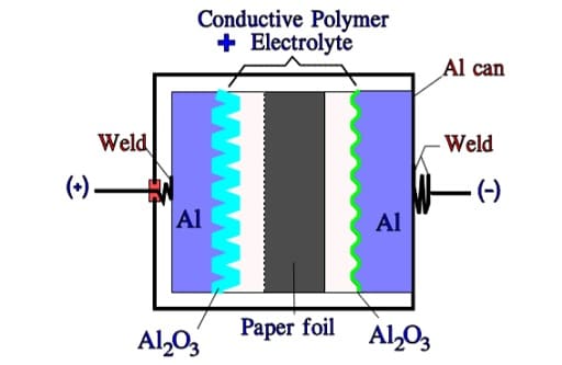
The most common styles are wound foil capacitors packaged in aluminum can as leaded or SMD termination styles. See Figure 1. and 2.
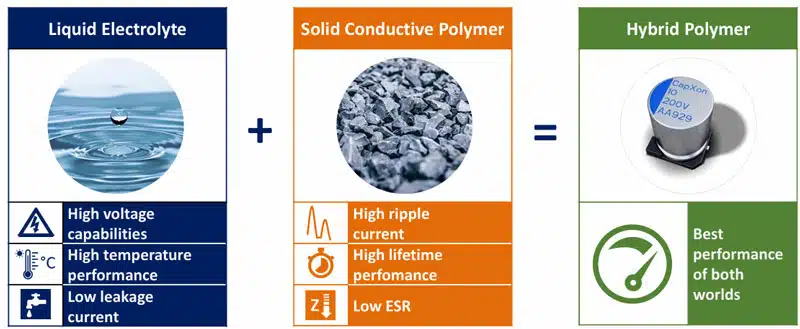
Electrolyte can be wet, gel (TCNQ salt), solid (conductive polymer) or hybrid (combining wet and conductive polymer) based:
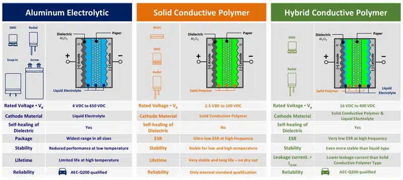
As a mix of the two worlds, the hybrid polymer technology offers for wide range of applications currently the best performance of high capacity storage components:
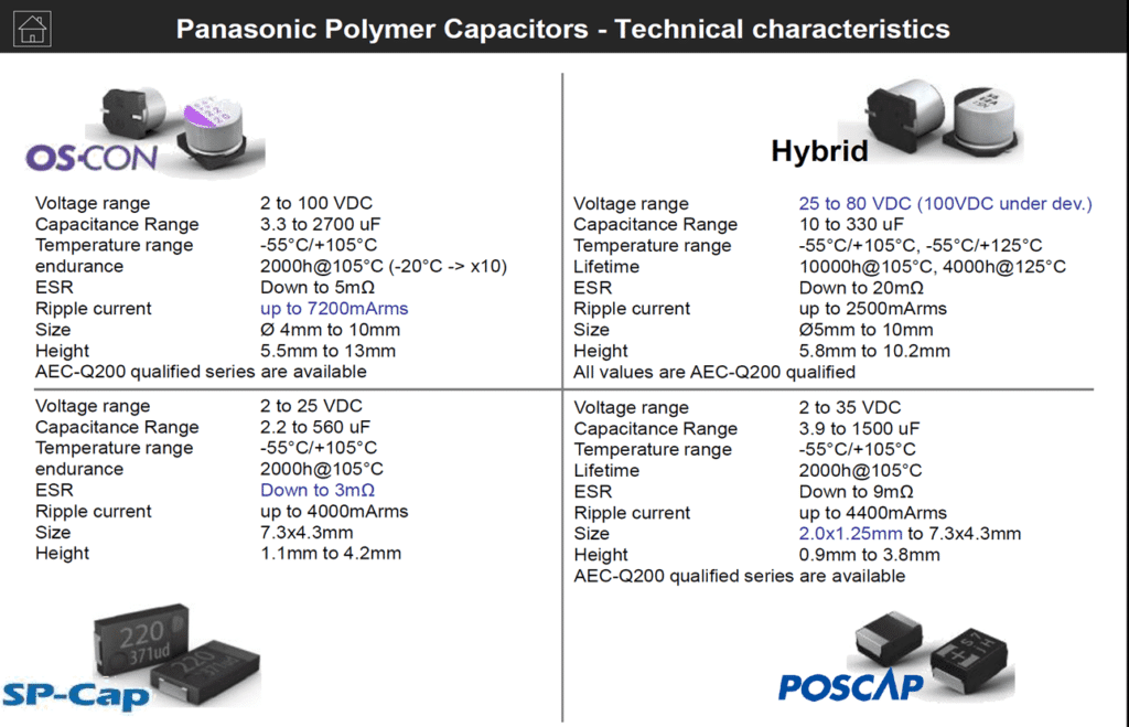
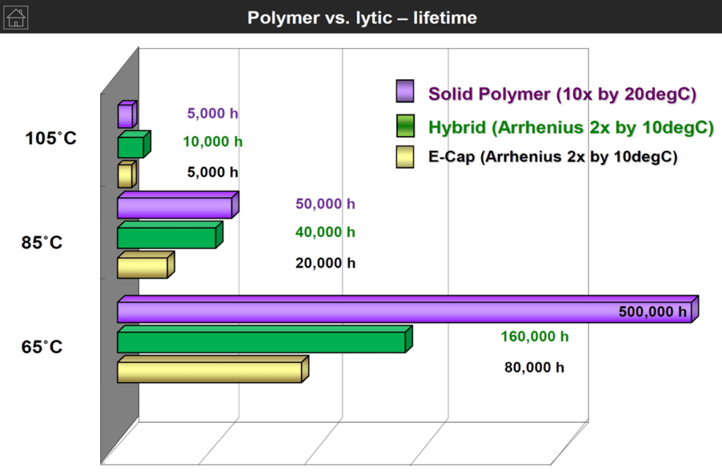
Panasonic, one of supplier of all aluminum and tantalum polymer capacitor technologies provide comparison of its technologies as follows:
- OS-CON is a TCNQ salt electrolyte
- Hybrid combine wet and polymer electrolytes
- SP-Cap is a solid polymer chip capacitor
- POSCAP is a tantalum polymer capacitor
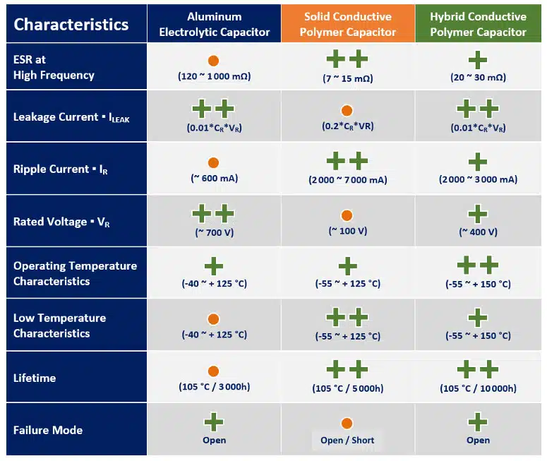
The following chart on Figure 3. is demonstrating lifetime with temperature comparison of wet vs polymer vs hybrid aluminum capacitors that can be helpful for a specific application selection guide.
DCL and balancing
Aluminum electrolytic capacitors leakage current and balancing is explained in more details in a paper below:
DCL of Aluminum Electrolytic Capacitors – by Dr. Arne Albertsen from Jianghai Europe Electronic Components GmbH
Manufacturing Process:
The production process starts with mother rolls. First, the etched, roughened and pre-formed anode foil on the mother roll as well as the spacer paper and the cathode foil are cut to the required width.
The foils are fed to an automatic winder, which makes a wound section in a consecutive operation involving three sequential steps: terminal welding, winding, and length cutting. In the next production step the wound section fixed at the lead out terminals is soaked with electrolyte under vacuum impregnation.
The impregnated winding is then built into an aluminum case, provided with a rubber sealing disc, and mechanically tightly sealed by curling. Thereafter, the capacitor is provided with an insulating shrink sleeve film. This optically ready capacitor is then contacted at rated voltage in a high temperature post-forming device for healing all the dielectric defects resulting from the cutting and winding procedure.
After post-forming, a 100% final measurement of capacitance, leakage current, and impedance takes place. Taping closes the manufacturing process; the capacitors are ready for delivery.

Wet Aluminum Electrolytic Capacitors
Introduction
Wet aluminum (Al) electrolytic capacitors continuously generate hydrogen gas under operation and while stored with even a small residual charge. That hydrogen must be able to diffuse and exit the package or it will rupture. Thus conventional wet Al electrolytics must not be hermetic sealed. The diffusion takes place through the non-hermetic lid that usually has a rubber packing in the pressure seal against the can edge.
Larger size cans are also supplied with a safety vent that provides for relief in the instance of very critical gas generation. There are also special, high reliability hermetic Al electrolytic available on the market based on improvements of electrolytes and gas absorbing compounds.
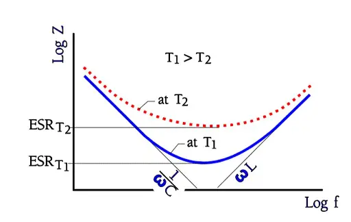
In catalog sheets for different electrolytic types it’s usual to show impedance versus frequency at different temperatures. The axes are given a logarithmic scale and look in principle like the one in following Figure 5. where the ESR at several temperatures can also be read.
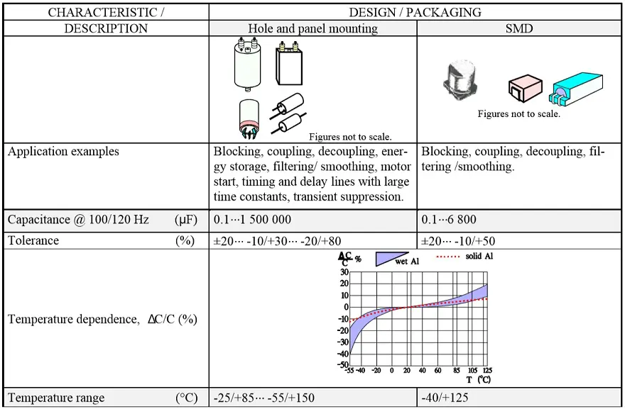
The capacitance stability versus time and temperature is comparatively poor. Tolerances must be adjusted, from ±20 for the best professional types to –20/ +80% for some commercial makes. Rated voltages exist from 3 to above 500 V DC.
The maximum permissible reverse voltage is:
- 0.5 V for VR ≤ 7 V
- 1 V for VR > 7 V
The reverse voltage figures apply up to the rated temperature. Then a proper derating is recommended. Losses often are large and strongly temperature and frequency dependent. Figure 5. shows how the impedance versus frequency curve at increasing frequencies approaches and finally reaches the ESR contribution at temperature dependent levels. This occurs somewhere between 1 to 100 kHz, depending on capacitance size and temperature.
Recent examples of new solid-polymer or hybrid electrolytes with improved electrical conductivity present on the market. Nevertheless, the conventional wet Al electrolytic capacitors are one of the lowest cost capacitor technologies on the market and still under high volume use or in higher voltage applications where there is no polymer/hybrid electrolyte alternatives.
Examples of some typical applications of wet Al electrolytics are as follows: smoothing, filtering in Switched Mode Power Supplies (SMPS; low ESR necessary), coupling/decoupling , energy storage, timing and delay circuits with large time constants.
Properties
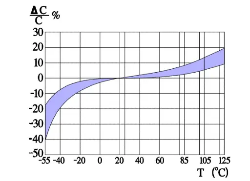
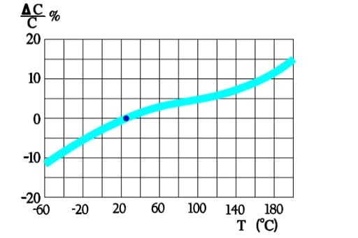
Figure 6. shows a strong capacitance deviation at lower temperatures. It is caused by the increasing resistivity of the electrolyte. Note that the temperature ranges vary and with that the temperature dependence of corresponding electrolytes also varies. Some types can withstand –55/+150 °C, others only –25/+85. Most common temperature ranges are –40/+85 and -40/+105 °C.
Capacitance versus temperature
Capacitance versus frequency

Note in Figure 7. how the low voltage – high capacitance, characterized by large foil surfaces and finer etching, demonstrates a higher frequency dependence while the opposite decreases this dependence.
Tan δ versus temperature
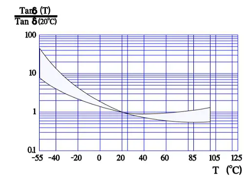
Figure 8. shows the normalized Tan δ value, i.e., the multiplier for Tan δ compared with the reference value at 20 °C. Thus, according to the curve, in worst case Tan δ 55°C is approximately 50 times larger than Tan δ+20°C.
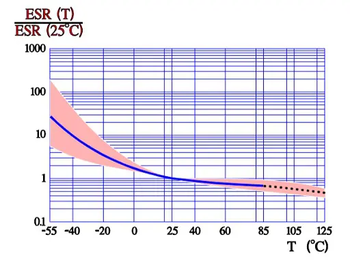
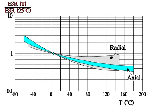
According to the formula Tan δ = ESR x ωCs which means that at a fixed frequency the ESR versus temperature curve will have the same appearance as the one of Tan δ (Figure 9.).
ESR versus temperature
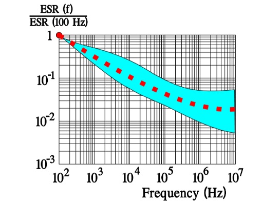
ESR versus frequency
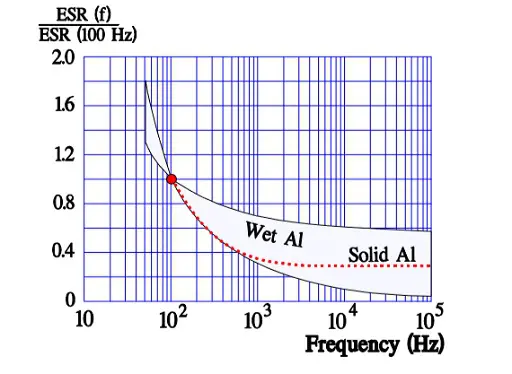
In Figure 10. the ESR versus frequency is shown as a ratio between the 100 Hz value and the ones at other frequencies (a multiplier of the reference value). It applies at room ambient temperatures and above and will differ slightly at lower temperatures. The strong slope of the curve range at lower frequencies depends mainly on the oxide losses. Just for caparison a typical curve also for solid Al is shown.
ESR and ripple currents
In filter applications the capacitors will conduct considerable AC currents caused by superimposed ripple. The ripple current creates heat in the capacitor ESR. Therefore a maximum ripple current IR-max is specified at reference conditions: 100 or 120 Hz and at some higher temperature, for example 85 °C or the upper category temperature Tuc (Figure 6.). With reference data in the data sheets as a starting-point it is then possible to convert these values to operational condition values.
The maximum ripple current is specified to create a generated average core temperature rise of 10 °C above the allowable maximum ambient temperature. This margin, however, varies strongly with can size and manufacturer. With respect to proper derating this margin should not be utilized. When the ripple current frequency rises, the ripple current capability increases. That depends on a corresponding decrease of the ESR (Figure 10.) that has a negative TC, mainly caused by the electrolyte, and this will consequently lead to a decreasing ESR when the temperature rises (for example, at higher ripple currents) (Figure 9.). If we, for example, specify an IR-max at 100 Hz and permit 1.4 x IR-max at 10 kHz this is possible just because ESR10kHz ≈ ½ESR100Hz. For (1.4 x IR-max )2 x ½ ESR100Hz ≈ 2 x ½ x (IR-max )2 x ESR100Hz = (IR-max)2 x ESR100Hz. But, please, check the manufacturer’s data sheets. There are differences between both styles and manufacturers.
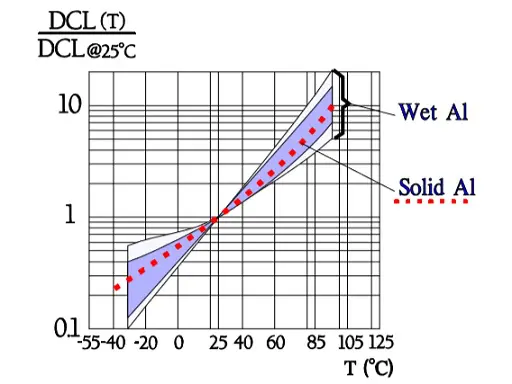
Leakage current
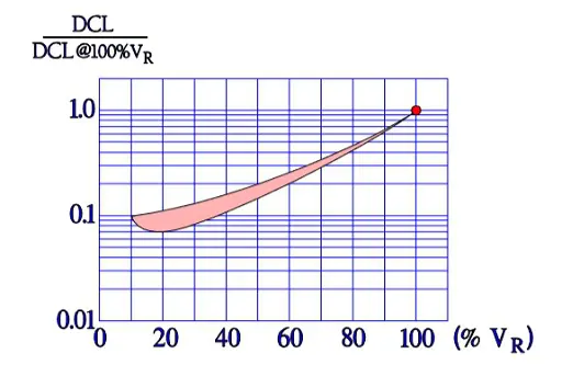
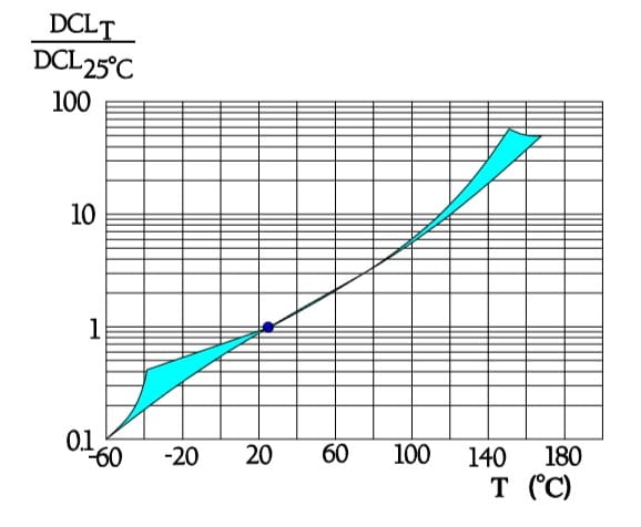
Also the important parameter leakage current varies with the environmental conditions. When temperature increases from the lower to the upper limit of the temperature range, leakage current rises approximately two orders of magnitude (Figure 11.). Next figure shows the ratio of DCL versus applied DC voltage and DCL at 100% VR.
Leakage current versus temperature
Leakage current versus DC voltage
Heat generation
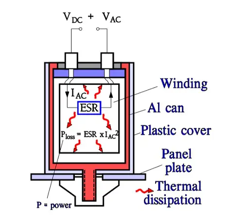
Aluminum electrolytics also are manufactured with high CV products in correspondingly large cans. If they are loaded with a superimposed ripple voltage heat generation from the power ESR x IAC2 might be troublesome. The rise of temperature will be largest in the center of the winding, i.e. the capacitor Hot Spot, and must not exceed certain values. Therefore a maximum AC current value is specified at 100 or 120 Hz and sometimes also at 20, 40 or 100 kHz. Furthermore it’s usual to state the maximum ESR at these frequencies. A schematic of the heat generation principle is shown in Figure 13. The components of ESR are shown in Figure 14.
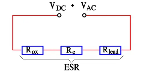
- Rox = resistance in the dielectric oxide layer
- Re = resistance in the electrolyte and paper separator
- Rlead = resistance in electrical conduction paths.
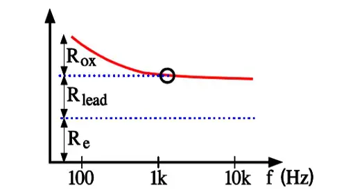
Above all it’s the dielectric oxide losses that are frequency dependent and cause the general appearance of the ESR curve shown in Figure 10. In more detail the frequency dependence can be illustrated as in Figure 15. where one can note how the oxide losses, on the whole, end above 1.5 kHz.
There are for high-reliability styles information about their thermal capacitance and resistance. If we know the can and ambient temperatures then the Hot Spot temperature of the capacitor can be calculated more thoroughly. A less accurate but more simple calculation says that
Thsp – Ty » Ty – Ta⋅⋅⋅⋅⋅⋅⋅⋅⋅⋅⋅⋅⋅⋅⋅⋅⋅⋅⋅⋅⋅⋅⋅⋅⋅⋅⋅⋅⋅⋅⋅⋅⋅⋅⋅⋅⋅⋅⋅⋅⋅⋅⋅⋅⋅⋅⋅⋅⋅[1]
Where:
- Thsp = Hot Spot temperature
- Ty = surface temperature of the can
- Ta = ambient temperature (Figure C3-35)
Life calculation
The Life (L0) for a wet Al electrolytic is stated in the catalog sheets as the number of hours at the maximum temperature, Tuc. If, for example, the stated L0 = 2000 h @ 85 °C, we get the Life at 35°C by means of the formula as
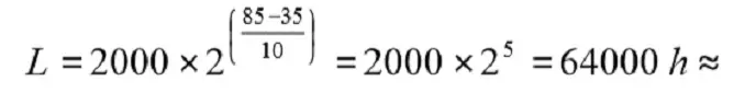
7 years
Thus the formula says that Life is doubled for a temperature decrease ∆T = 10 °C. We repeat that the formula is just a rule of thumb (Arrhenius relationship) and no accurate calculation.
See more details in video: Estimating and Modelling Lifetime of Aluminum Electrolytic Capacitors for any Ripple Current and Temperature
Mounting
Large can electrolytics with a safety vent preferably should be mounted in an upright or horizontal position, thus preventing electrolytic liquids from obstructing any gas diffusion.
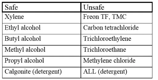
Cleaning solvents
Penetrating contaminations, especially from halogenbased washing agents, sooner or later may lead to a short circuit. Exposed to an electric field they will be converted electrochemically to free chlorides that will cause corrosion, a subsequent increase in leakage current and finally a short circuit. Because destruction takes place only when the capacitor is electrically operated, failures unfortunately occur only in the field and after some time. In order to avoid a suction effect during the washing one shall make sure that the component has a lower temperature than that of the washing bath.
Failure modes
The most common failure is drying escape of the electrolyte. Drying first manifests itself as a high ESR. For it’s not only hydrogen gas that diffuses through the sealings to the lid of the aluminum electrolytic. The electrolytic liquid also diffuses through the non-hermetic lid. One leading manufacturer has solved this problem to a great extent by utilizing rubberized laminated paper washers instead of conventional rubber seals. However, diffusion and hydrogen development will take their tribute. Gradually the electrolyte dries up and left will be only a kind of resistor.
Experiences indicate that an electrolyte loss of 20% increases the ESR approximately 100%! The wet Al electrolytic capacitor is the one component type that has the most distinct life limitation. Beyond a certain time the capacitor ceases to be a capacitor. At tests performed at the maximum temperature one may get an idea of the diffusion rate and thus the life by weighing the part and calculating the electrolyte loss during the test. Wet Al electrolytics in chip design had some problems when they first were introduced on the market. There were examples of how certain types lost half of the electrolyte supply during the soldering process.
Now these problems certainly are overcome, but make sure the manufacturer is in command of the difficult manufacturing process of chip sealing. Open circuits caused by fatigue fractures in internal contact strips between winding and terminals during vibration/bump are not too unusual. Chloride contamination of foils from clammy hands or penetrating cleaning agents can cause high leakage currents and finally short circuiting.

Solid Aluminum Electrolytic Capacitors, Polymer, Hybrid and TCNQ Salt
Solid Aluminum Electrolytic Capacitors with Conductive Polymer or TCNQ Salt
Polymer Electrolytic Capacitors
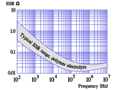
Most common variant of a solid electrolyte is conductive polymer electrolyte. The aluminum oxide on an etched and formed foil is covered with an electrically very conductive and doped polymer. The polymer can withstand temperatures up to +105 °C. The ESR of the capacitor is several ten powers better than that of the wet electrolytic types. Its temperature dependence is negligible, but the frequency dependence is more pronounced (Figure 16.).
The polymer electrolytic capacitor is manufactured in a can or a chip construction with ESR range from 4.5mΩ to 70mΩ, voltage range 2 V to 16 V and capacitance from μF to hundreds of μF. Recommended derating is to use ≤ 80% of VR. The capacitor must not be subjected to any reverse voltage. In case of a short-circuit the local heat generation from the current in the failure spot will be so high that the polymer either will oxidize or will be de-doped and thus creates an insulating “patch” over the failure area. Thus, the capacitor self-heals.
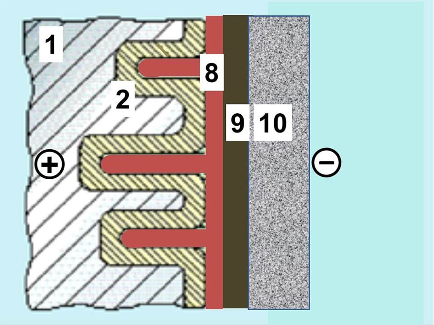
An advantageous chip design is the flat stacked type shown in Figure 17. It consists of stacked aluminum plates that have been etched and supplied with an anodic oxidation. The tunnel like structure is covered with a polymerized thin conductive film. Between this film and the following silver paint is added a graphite layer serving as a buffer between the polymer and the silver coating.
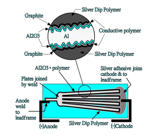

The aluminum plates are dipped in a silver epoxy that covers the polymer and graphite surface and fills up the spongy structure of the aluminum plates. The device is then molded in the same plastic epoxy as the one used in solid tantalum SMDs. This construction has an excellent volumetric efficiency. There is a significant difference between this construction and that of a solid sintered tantalum capacitor.
In the latter case the current has to pass “horizontally” through the MnO2 cover to charge the inner capacitive elements in the porous tantalum pellet. In the stacked aluminum construction the current passes “vertically” through the silver, carbon and polymer layers to the inner capacitive elements in the etched tunnels as shown in Figure 18.
The vertical current paths means a considerably reduced ESR. Such capacitors are capable of a single-digit ESR in the 100 kHz region.
The polymer capacitor is well established and has its greatest advantages in smoothing and noise reduction applications. For high reliability applications, however, its capability in high-shock mechanical environments must be evaluated.
Hybrid Aluminum Electrolytic Capacitors
There also exists a hybrid version of the polymeric style. It has a construction of principle as shown in Figure 19. The combination of a liquid electrolyte and a polymer reduces the ESR at the same time as the self-healing properties are retained due to the ion movability.
This type is growing presence on the market as Al can construction (SMD variant is also available) due to its improved robustness to IR reflow mounting conditions compare to Al pure polymer electrolyte solution.
TCNQ Salt Aluminum Electrolytic Capacitors
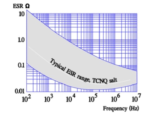
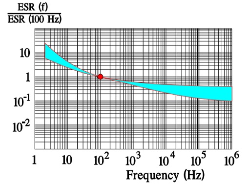
Like the polymer electrolyte the semiconducting organic salt TCNQ has also been available on the market for a number of years under trade name OSCON. The winding is impregnated at a relatively high temperature with melted salt that at cooling is transformed into a solid state. Its ESR is better than that of wet electrolyte but somewhat poorer than that of the polymer electrolyte. The temperature dependence of the ESR is negligible but its frequency dependence more pronounced (Figure 20.). Note its similarity with the polymer electrolytic.
This capacitor is sensitive both to mechanical shocks and ESD. It can endure certain vibration environments. Immediately after soldering it should not be subjected to handling due to the heat influence on the structural strength of the electrolyte/ dielectric system. The highest rated voltage should be derated linearly from 25 V at 85 °C to 20 V at 105 °C.
- Capacitance range 0.1⋅⋅⋅680 µF
- Temperature range -55/+105°C
- Maximum rated voltage 30 V DC
- ESR, frequency and temperature dependence ≈ that of the polymer capacitor.
Self-healing may occur at short-circuiting. In the failure spot the short-circuit current generates so much heat that the salt decomposes or disappears and thus creates a local insulation area. The capacitor must not be subjected to surge currents or to any overvoltage. Prolonged load at high temperatures will lead to capacitance decrease or in the worst case to open mode. TCNQ salt may also present some risk to environment and ROHS regulation due to presence of cyanide salts. Thus polymer/hybrid types are the main growing aluminum electrolytic capacitor technologies at present stage.
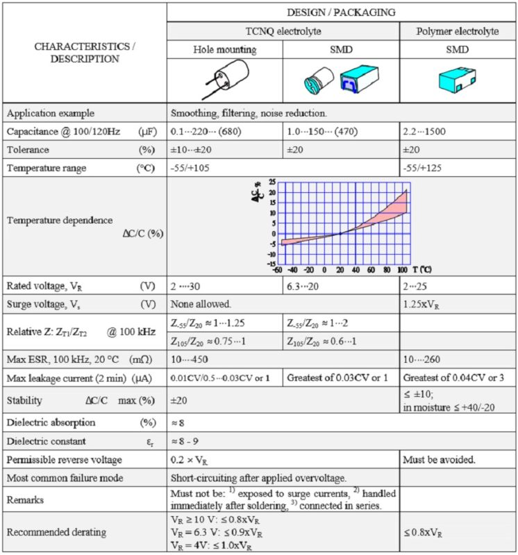
Table 3. SOLID ALUMINUM ELECTROLYTIC CAPACITORS, POLARIZED, with CONDUCTIVE POLYMER or TCNQ SALT
Solid Aluminum Electrolytic Capacitors (SAL) with Manganese Dioxide MnO2 (obsolete capacitor technology)
The SAL are aluminum electrolytic capacitors with anodic oxidized aluminum oxide as dielectric and with the semiconducting solid manganese dioxide as electrolyte. They are made of etched and formed aluminum anodes, which are folded for the dipped pearl types or wound into a roll for the axial style. The solid manganese dioxide electrolyte is formed onto this roll in a pyrolytic process, similar to that for solid tantalum capacitors.
SAL-capacitors were developed and introduced in the market in the 1960s by Philips. Up until December 30, 2015, it was a single source product manufactured by Vishay.
As of December 31, 2015 the SAL are end-of-life and have ceased production. Nevertheless, we still list the technology features here for comparison and overview.
Introduction
The electrolyte is a solid one. Thus, life is independent of drying effects and leakage currents and theoretically unlimited. Storage has no impairing effect on the dielectric. The stability is much better than that of wet types. The capacitance tolerance is ±20%. The price is high.… Compared to solid tantalums the price for solid aluminum (Al) electrolytics of the same CV product is between two and three times higher. The solid electrolyte doesn’t penetrate the pores of the highly etched aluminum foil equally well as a wet one. Its conductivity, however, is between one and two orders of magnitude larger than that of the wet electrolyte and its temperature dependence smaller.
Thus, the solid Al electrolytic is relatively insensitive to the pore effect that in wet Al electrolytics creates a deep network of series and parallel resistances as shown in electrolytic capacitors overview. The capacitor can’t stand any breakdowns. This requires large margins between the forming and rated voltages. The forming rate usually is 2 to 3 times and the rated voltage maximum 40 V DC. Unlike solid tantalums the capacitor is relatively insensitive to pulse loads which, among other things, depends on its higher ESR that reduces the need for an additional circuit impedance.
Nevertheless, just as in solid tantalums, very high pulse currents can initiate a fire. There were two construction styles on the market, the epoxy encapsulated radial types for maximum 175 °C and the axial aluminum can type designed for maximum 200 °C. The radial lead design has a stacked aluminum plate construction which renders a very low ESL (equivalent series inductance). It ranged from 9 to 20 nH. The cylindrical can has a winding of anode and cathode foils plus glass fiber spacers. The reliability of the cylindrical can types is high. Of these there are designs with epoxy fillings intended for extreme acceleration and shock stress.
Properties
Both the radial and the axial lead types are represented in Figure 22.
In comparison with wet aluminum electrolytics (Figure 9.) ESR of the solid ones have a less pronounced temperature dependence as shown in Figure 23.
Capacitance versus temperature
ESR versus temperature
ESR versus frequency Typical normalized diagrams are shown in Figure 24. and 25. The former concerns the radial lead designs with their lower ESL and higher operating frequency range.
Note the lower frequency range of the following axial lead design. The steeper slope of the diagrams in the lower part of the frequency range depends on the oxide losses (Figure 25.).
Leakage current versus temperature
Reverse voltage
The permissible reverse voltage is stated to be:
- @ ≤ 85°C max 0.3 x VR
- @ 85 → 125°C from max 0.3xVR → max 0.15xVR
Failure modes
Epoxy-dipped types with radial leads are sensitive to mechanical forces applied on the leads at mounting. Inappropriate handling results in an increase of the leakage current.