


This post provides deeper look into capacitor based power factor correction circuits and power factor correction (PFC) capacitors.
Some of the AC power consumed by inductive loads is used to maintain magnetic reversals due to phase shift between current and voltage. This energy can be considered as wasted energy since it is not used in performing useful work.
Power factor correction circuits are used to minimize reactive power and enhance the efficiency with which inductive loads consume AC power.
Capacitors are essential components in power factor compensation circuits, and this article will explore some design considerations when using these components for power factor correction.
Power Factor Correction Circuits
Reactive Power in Inductive Loads
Inductive loads such as chokes, motors, inductive heating equipment, generators, transformers, and arc welding equipment produce an electrical lag that is commonly referred to as inductance. This inductance causes a phase difference between current and voltage. Figure 1 shows current and voltage waveforms for a load with zero lag (purely resistive load).

As a result of phase shift due to inductance, there are times when current and voltage have different signs. During such times, negative energy is generated and fed back into the power supply network. When the two regain same sign, a similar amount of energy is required to generate the magnetic fields. The energy that is lost due to magnetic reversals in inductive loads is commonly referred to as reactive power.
Inductive AC loads are broadly classified into linear and non-linear devices. For linear loads, the current waveform and voltage waveform have matching sinusoidal profiles. Figure 2 shows current and voltage waveforms for a typical linear load. On the other hand, since non-linear loads draw current at different frequencies, the current and voltage waveforms are different. For most non-linear loads, the current waveform is usually non-sinusoidal. Figure 3 shows current and voltage waveforms for a non-linear load.


Some examples of linear electrical loads include heating equipment, motors, and incandescent lighting devices. Non-linear devices include variable frequency drives, DC drives, programmable controllers, arc-type lighting devices, induction furnaces, uninterruptible power supplies, and personal computers. Non-linear electrical loads are known to be a major cause of harmonic distortions in power distribution systems.
Power Factor
The efficiency with which electrical devices or installations consume AC power varies. Some loads utilize power efficiently, while others waste a significant portion of the power that they consume. Power factor is used to describe the efficiency with which loads consume AC power. This dimensionless quantity ranges between 0 and 1.
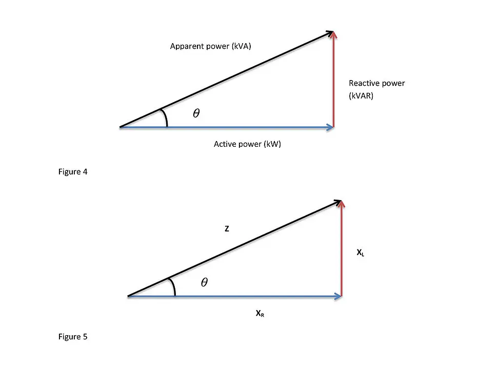
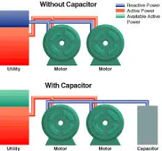
As shown in Figure 4 and Figure 5, the total AC power, also commonly known as apparent power, consumed by an electrical device or equipment depends on two components: useful power (active power) and reactive power. The useful power refers to the power that a device needs to accomplish a task. On the other hand, reactive power does not produce useful work. The useful power is usually measured in kW while the reactive power is measured in kVAR.
As shown in Equation 1, the power factor is equal to the ratio of active power (useful power) to total power (apparent power) drawn by an electrical device or equipment.
It can be shown mathematically that the power factor is equal to the cosine of angle θ (Equation 2). The closer this ratio is to 1.0, the higher is the efficiency of the device or equipment.

For an ideal electrical load, the power factor is equal to 1.0 (unity power factor). This means that all the power drawn by a load is used to do useful work. However, it is difficult for an actual electrical load to achieve that. The impedance for the load represented by Figure 5 is given by Equation 3, where XL is the inductive reactance and is given by Equation 4.
Why is it difficult for an electrical load to achieve unity power factor? Most electrical loads have inherent reactive properties that make it difficult for them to achieve the ideal power factor. To overcome this limitation, power factor correction circuits are added to a network to compensate for a load’s reactive characteristics.
Power Factor Correction (Compensation)
Electrical loads that have a low power factor consume more power that it is needed to perform a task. This can result in a considerable power loss in a network and high transformer losses. Such increases in energy consumption increase the cost of running equipment or installations. Poor power factors also cause a power distribution network to have increased voltage drops. It is common for power suppliers to penalize industries whose power factor is below a specified value.
Electricity suppliers encourage industrial consumers to improve their power factor for various reasons. To start with, improving power factor can help to cut the electricity bill by a significant margin. Secondly, a high power factor helps to minimize efficiency losses in a consumer’s transformers. Thirdly, adding power factor correction system helps to boost the effective capacity of a consumer’s electricity network. Lastly, a high power factor helps to increase the service life of electrical equipment.
A power factor compensation network lessens the power demanded by a load thus improving the overall power factor. The compensation network enables electrical loads to achieve a good power factor, typically between 0.95 and 0.98. A power factor of 0.85 and below is usually considered by utility companies as a poor power factor.
Power Factor Improving Methods and PFC Capacitors
There are various methods of improving the power factor of a load or an installation. One of the commonly used methods involves adding power factor correction capacitors to the network. Figure 6 shows a simple circuit consisting of an AC source and an inductive load.
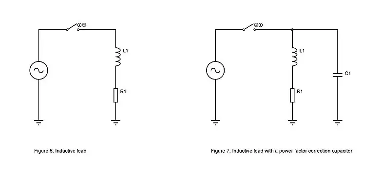
How does a capacitor help in improving the power factor? In an AC circuit, magnetic reversal due to phase difference between current and voltage occurs 50 or 60 times per second. A capacitor helps to improve the power factor by relieving the supply line of the reactive power. The capacitor achieves this by storing the magnetic reversal energy.
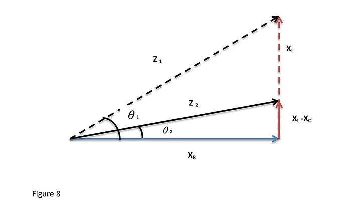
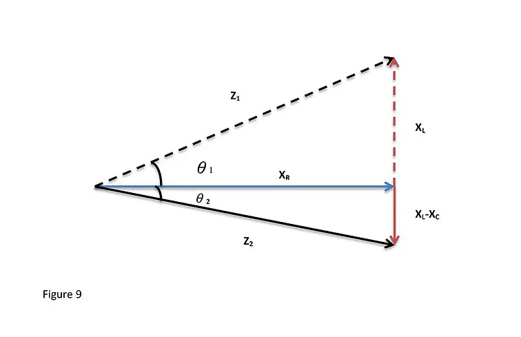
Figure 7 shows an inductive load with a power factor correction capacitor. Figure 8 above illustrates the improvement in power factor when the capacitor is added to the circuit. The impedance for a circuit with a power factor compensation capacitor is given by Equation 5, where XC is capacitive reactance and is given by Equation 6.
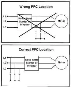
In most industries, a system of capacitors controlled by a power factor correction controller is installed for reactive power compensation. When designing a power factor correction system, it is important to avoid adding excess capacitance to the network. Adding excess capacitance to a circuit can lead to over-correction as illustrated in Figure 9.
Semiconductor devices are also widely used for power factor correction. Using semiconductor devices to a circuit to improve power factor is commonly referred to as active compensation. Overexcited synchronous machines are also commonly used to improve the power factor of a network.
As mentioned above most electrical loads, including transformers, welding sets, induction motors, and induction furnaces are inductive. Inductive loads require both working power, usually measured in kilowatts (kW), and reactive power, usually measured in kilo-volt-amperes-reactive (kVAR), to operate. The working power is used for performing the actual work, while reactive power is used for sustaining the magnetic field required by inductive loads. When combined, working power and reactive power form apparent power, usually measured in kilovolt-amperes (kVA).
Power factor is a measure of the efficiency with which electrical loads convert electrical power into useful work. It is a ratio of useful power (working power) to the total power (apparent power) supplied. A high power factor is an indicator that the electrical loads are utilising power efficiently, while a low power factor indicates that the connected electrical loads are utilising power inefficiently. A poor power factor results in significant energy wastage, and decreases the capacity of the electrical system. It can be caused by a phase difference between current and voltage at the terminals of an electrical load, or a distorted current waveform.
Power Factor Correction Solutions
A poor power factor due to induction motors, transformers, and other inductive loads can be corrected by connecting suitable capacitors. A poor power factor caused by distorted current waveform is corrected by adding harmonic filters. The process of creating the magnetic field required by an inductive load causes a phase difference between the voltage and the current. A capacitor corrects the power factor by providing a leading current to compensate the lagging current. Power factor correction capacitors are designed to ensure that the power factor is as close to unity as possible. Although power factor correction capacitors can considerably reduce the burden caused by an inductive load on the supply, they do not affect the operation of the load. By neutralising the magnetic current, capacitors help to cut losses in the electrical distribution system and reduce electricity bills.
A poor power factor due to induction motors, transformers, and other inductive loads can be corrected by connecting suitable capacitors. A poor power factor caused by distorted current waveform is corrected by adding harmonic filters. The process of creating the magnetic field required by an inductive load causes a phase difference between the voltage and the current. A capacitor corrects the power factor by providing a leading current to compensate the lagging current. Power factor correction capacitors are designed to ensure that the power factor is as close to unity as possibe. Although power factor correction capacitors can considerably reduce the burden caused by an inductive load on the supply, they do not affect the operation of the load. By neutralizing the magnetic current, capacitors help to cut losses in the electrical distribution system and reduce electricity bills.
To discourage energy wastage, some electricity distribution companies penalize consumers with a power factor that is below a specified value, and offer an incentive to consumers with a good power factor (usually above 0.95). This encourages consumers to install power factor correction equipment in their electrical systems. Benefits of adding power factor correction capacitors to electricity networks include reduced losses, improved voltage, increased system capacity, and reduced electricity bills. Key variables to consider when selecting capacitors for power factor correction include load type, load constancy, load size, load capacity, method of utility billing, and load starting methods.
Power factor correction capacitors are usually installed as banks of capacitors when substations or large facilities are involved. In the case of sinusoidal or linear loads, they can be installed as individual capacitors that are easy to install or replace, and do not require separate switching. On the other hand, capacitor bank installations have lower cost per kVAR, and provide exact power factor correction capacitance when automatic switching systems are used.
Depending on the needs of a particular substation or facility, fixed or automatically switched capacitor banks can be installed. A fixed power factor capacitor bank can be switched on when the inductive load is on, and off when the individual load is off. Such capacitors are energized only when power factor correction is needed. In facilities with multiple loads, load conditions and power factor correction needs change frequently. Automatic capacitor systems are suitable for such facilities. They prevent over-correction and under-correction.
Large inductive loads such as oil drilling rigs, wind turbines, large motors, arc furnaces and auto crushes have dynamic load characteristics. Such large dynamic loads demand sophisticated automatic capacitor systems with fast response capabilities. Transient-free automatic capacitor banks are used for power factor correction in applications where large inductive loads are involved. Harmonics can significantly reduce the life of capacitor banks. For loads that produce harmonics, a harmonic filter should be added. This filter removes unwanted harmonic frequencies from the electrical system.
Types of Power Factor Correction Capacitors
Capacitors for power factor correction are manufactured in a variety of types, sizes and designs. The most commonly used types are constructed using a metallized polypropylene film while a few employ metallized polyester film or paper.
Bi-metallized paper capacitors are commonly used in applications that demand robust power factor correction solutions. The special paper used for constructing these capacitors contains a thin layer of metal alloy. Sheets of paper are separated by a polypropylene film. These capacitors are constructed to withstand high temperatures and high harmonic content. Bi-metallized paper capacitors find many applications in power electronics. Metallized polyester film capacitors are compact, light and offer excellent capacitance stability. Although these capacitors are used primarily for DC applications, they are also suitable for AC line filtering and power factor correction.
Conclusion
Inductive loads such as transformers, generators, motors, chokes, and arc welding equipment produce an electrical lag that results in current and voltage having different signs. The energy required to maintain magnetic reversals in inductive loads is referred to as reactive power. Reducing reactive power by improving the power factor of an AC load helps to minimize the overall cost of running inductive loads. Capacitors are commonly used in industries to improve the power factor and minimize energy wastage.
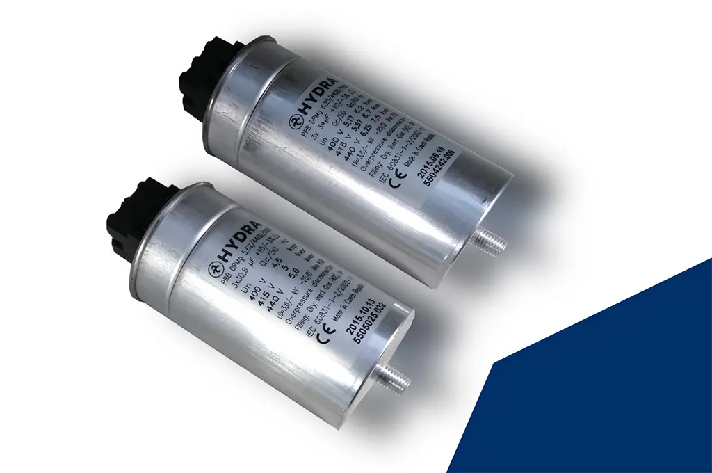
featured image credit: Hydra