

Passive Components Blog
No Result
View All Result
  • Home
  • NewsFilter
    • All
    • Aerospace & Defence
    • Antenna
    • Applications
    • Automotive
    • Capacitors
    • Circuit Protection Devices
    • electro-mechanical news
    • Filters
    • Fuses
    • Inductors
    • Industrial
    • Integrated Passives
    • inter-connect news
    • Market & Supply Chain
    • Market Insights
    • Medical
    • Modelling and Simulation
    • New Materials & Supply
    • New Technologies
    • Non-linear Passives
    • Oscillators
    • Passive Sensors News
    • Resistors
    • RF & Microwave
    • Telecommunication
    • Weekly Digest

    Bourns Introduces Automotive BMS Signal Transformer with Integrated Common Mode Chokes

    Itelcond Introduces High‑Voltage Aluminium Capacitors for Modern IGBT DC‑links

    Bourns Introduces Automotive Shielded Power Inductors for Compact DC‑DC Converters

    EMC Design Fundamentals: Safe Use of Varistors and Common Mode Chokes in Mains and Data-Line Filters

    Murata Unveils Lead Disc Ceramic Capacitors for Automotive Safety and EMI Suppression

    SCHURTER Releases Intelligent Three‑Terminal Fuses for Safer Li‑ion Battery Systems

    Can Copper Conductive Inks Displace Silver in Hybrid Electronics?

    Square-Wave Harmonics and RMS Currents in Power Converters

    LeanBOM: Practical Cross‑Technology Capacitor Search by Real Working Conditions

    Trending Tags

    • Ripple Current
    • RF
    • Leakage Current
    • Tantalum vs Ceramic
    • Snubber
    • Low ESR
    • Feedthrough
    • Derating
    • Dielectric Constant
    • New Products
    • Market Reports
  • VideoFilter
    • All
    • Antenna videos
    • Capacitor videos
    • Circuit Protection Video
    • Filter videos
    • Fuse videos
    • Inductor videos
    • Inter-Connect Video
    • Non-linear passives videos
    • Oscillator videos
    • Passive sensors videos
    • Resistor videos

    EMC Design Fundamentals: Safe Use of Varistors and Common Mode Chokes in Mains and Data-Line Filters

    Ferrite versus Nanocrystalline Power Inductor Cores: Turns, Gap and Size

    KYOCERA AVX Presents Antenna Integrator Studio Tutorial for Antenna Placement and RF Design

    Power Design Simulation Tools for Faster Inductor Selection and Loss Optimization

    EMC‑Compliant PCB and Connector Design Guidelines

    Why Isolated DC/DC Power Supplies Fail Late, Würth Elektronik Podcast

    Designing 800 V DC EMC Filters: Calculation, Simulation and Measurement

    Current Sense Transformer Datasheet and Design‑in Guide

    Designing a USB Type‑C Flyback Planar Transformer with Frenetic’s Planar Tool

    Trending Tags

    • Capacitors explained
    • Inductors explained
    • Resistors explained
    • Filters explained
    • Application Video Guidelines
    • EMC
    • New Products
    • Ripple Current
    • Simulation
    • Tantalum vs Ceramic
  • Knowledge Blog
  • Dossiers
    • AI Hardware Dossier
    • Power Converter Dossier
    • Automotive Dossier
    • Capacitor Dossier
    • Resistor Dossier
    • Inductor Dossier
    • Circuit Protection Dossier
  • Suppliers
    • Who is Who
  • PCNS
    • PCNS 2025
    • PCNS 2023
    • PCNS 2021
    • PCNS 2019
    • PCNS 2017
  • Events
  • Home
  • NewsFilter
    • All
    • Aerospace & Defence
    • Antenna
    • Applications
    • Automotive
    • Capacitors
    • Circuit Protection Devices
    • electro-mechanical news
    • Filters
    • Fuses
    • Inductors
    • Industrial
    • Integrated Passives
    • inter-connect news
    • Market & Supply Chain
    • Market Insights
    • Medical
    • Modelling and Simulation
    • New Materials & Supply
    • New Technologies
    • Non-linear Passives
    • Oscillators
    • Passive Sensors News
    • Resistors
    • RF & Microwave
    • Telecommunication
    • Weekly Digest

    Bourns Introduces Automotive BMS Signal Transformer with Integrated Common Mode Chokes

    Itelcond Introduces High‑Voltage Aluminium Capacitors for Modern IGBT DC‑links

    Bourns Introduces Automotive Shielded Power Inductors for Compact DC‑DC Converters

    EMC Design Fundamentals: Safe Use of Varistors and Common Mode Chokes in Mains and Data-Line Filters

    Murata Unveils Lead Disc Ceramic Capacitors for Automotive Safety and EMI Suppression

    SCHURTER Releases Intelligent Three‑Terminal Fuses for Safer Li‑ion Battery Systems

    Can Copper Conductive Inks Displace Silver in Hybrid Electronics?

    Square-Wave Harmonics and RMS Currents in Power Converters

    LeanBOM: Practical Cross‑Technology Capacitor Search by Real Working Conditions

    Trending Tags

    • Ripple Current
    • RF
    • Leakage Current
    • Tantalum vs Ceramic
    • Snubber
    • Low ESR
    • Feedthrough
    • Derating
    • Dielectric Constant
    • New Products
    • Market Reports
  • VideoFilter
    • All
    • Antenna videos
    • Capacitor videos
    • Circuit Protection Video
    • Filter videos
    • Fuse videos
    • Inductor videos
    • Inter-Connect Video
    • Non-linear passives videos
    • Oscillator videos
    • Passive sensors videos
    • Resistor videos

    EMC Design Fundamentals: Safe Use of Varistors and Common Mode Chokes in Mains and Data-Line Filters

    Ferrite versus Nanocrystalline Power Inductor Cores: Turns, Gap and Size

    KYOCERA AVX Presents Antenna Integrator Studio Tutorial for Antenna Placement and RF Design

    Power Design Simulation Tools for Faster Inductor Selection and Loss Optimization

    EMC‑Compliant PCB and Connector Design Guidelines

    Why Isolated DC/DC Power Supplies Fail Late, Würth Elektronik Podcast

    Designing 800 V DC EMC Filters: Calculation, Simulation and Measurement

    Current Sense Transformer Datasheet and Design‑in Guide

    Designing a USB Type‑C Flyback Planar Transformer with Frenetic’s Planar Tool

    Trending Tags

    • Capacitors explained
    • Inductors explained
    • Resistors explained
    • Filters explained
    • Application Video Guidelines
    • EMC
    • New Products
    • Ripple Current
    • Simulation
    • Tantalum vs Ceramic
  • Knowledge Blog
  • Dossiers
    • AI Hardware Dossier
    • Power Converter Dossier
    • Automotive Dossier
    • Capacitor Dossier
    • Resistor Dossier
    • Inductor Dossier
    • Circuit Protection Dossier
  • Suppliers
    • Who is Who
  • PCNS
    • PCNS 2025
    • PCNS 2023
    • PCNS 2021
    • PCNS 2019
    • PCNS 2017
  • Events
No Result
View All Result
Passive Components Blog
No Result
View All Result

Toroidal Inductors, Current Compensated Chokes, Common Mode Chokes and Beads

15.7.2026
Reading Time: 12 mins read
A A

Coils wound on toroids have due to the closed magnetic circuit, a high inductance and thus a good attenuation effect. If they are connected into a mains network in order to block or suppress interference of any frequency the choice of inductor must be determined by the kind of interference that applies. This article discuss construction and its impact of toroidal inductors, current compensated chokes, common mode chokes and beads.

Interference Background

We have to deal with either common mode / asymmetrical interference or differential mode / symmetrical interference.

RelatedPosts

Planar vs Conventional Transformer: When it Make Sense

Why Power Inductors Use a Ferrite Core With an Air Gap

Thermal Modeling of Magnetics

If we have a noise or interference source in a network that produces interference currents via short circuiting parasitic capacitance in, for example, the load, the two interference types may be illustrated with Figure 1.

The cure for this kind of interference current might be use of chokes combined with X- and Y- safety capacitors, i.e., capacitors intended for interference suppression in the mains. Asymmetrical interference is best rectified by a so called current compensated choke, where two counteracting windings cause the load current to create two opposing magnet fluxes. Those two fluxes cancel each other out. Any saturation risk is out of the question.
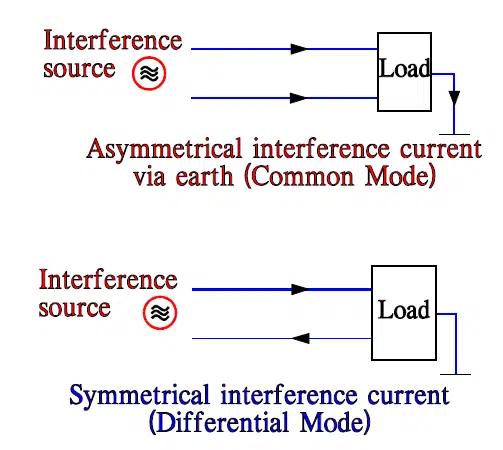
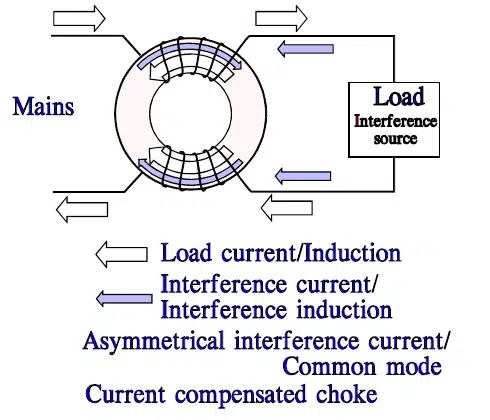
Figure 1. Asymmetrical (common mode) and symmetrical (differential) interference.
Figure 2. Asymmetrical interference on toroidal core

This method allows high permeability ferrites and subsequent high inductance. For asymmetric interference signals the inductance of the two windings co-operate and produce approximately 3.5 times higher inductance than a separate winding.

Note that the opposing fluxes from the load current create certain magnetic stray fluxes around the coils. This is illustrated in following figure 3.

Figure 3. Stray flux around a current compensated choke.
Figure 4. Symmetrical interference on toroidal core.

When there is a symmetrical interference (Figure 4.) we can’t use a current compensated choke. The fluxes of the load and interference currents will co-operate inside the toroid. In order not to come near magnetic saturation ferrites, with low to medium high permeability have to be used.

Current Compensated Chokes

Saturation effects caused by high signal currents, or DC current super imposed on the signal, reduce the effectiveness of the choke. The use of standard inductors in the signal path adversely impairs the useful signal. Current compensation circumvents these disadvantages. In current compensation, the “useful return current” must be passed through the choke. In this way, the useful current does not contribute to the magnetization of the core. See Figures 2. and 5.
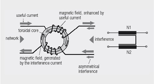
Figure 5. Construction and circuit diagram of a current compensated choke

Current-compensated chokes can be manufactured with different ferrite geometries; the best known are toroidal ring core and ribbed core. Different core materials enable their use in various frequency ranges. A very well known component, but one not designed as a common mode choke, is the snap ferrite or the split ferrite sleeve.

The effect of current-compensated chokes on coupled interference is, above all, used for data and signal lines. They are often the only option to avoid the interference suppression component affecting the useful signal.

see also webinar video: https://passive-components.eu/common-mode-choke-parameters-explained-we-webinar/

Current Compensated Choke Types

There is a wide range of current compensated choke types. Here is an overview of the most common types.

SMD Common Mode Noise Suppressor

The SMD Common Mode Noise Suppressor is usually not based on a ring core, either in size 0805 or 1206. Only for this reason it is possible to achieve such a compact current-compensated component. However, as it is a closed ferrite material system, the stray field remains negligibly small. Typical applications for the SMD common mode noise suppressors are USB, Firewire or High Speed Data Lines.

SMD Common Mode Noise Suppressor (Würth Elektronik WE-CNSW)

Current-Compensated SMD filter

current-compensated SMD line filters (Würth Elektronik WE-SL series)

In contrast to SMD common mode noise suppressors, the current-compensated SMD line filters include ring cores. As a result, stray fields can almost be excluded. The different geometries and, above all, the very flat package heights of the various types, offer potential solutions for every application. High current ratings, as used in low-voltage applications, are also available.

Despite their compact construction, the current-compensated SMD line filters can also offers 4x current-compensated versions.

NiZn Core Current-Compensated SMD Filter

The NiZn current-compensated SMD line filters offers high in common mode impedance with a smaller footprint than MnZn types. NiZn ferrite base material provides a wider working temperature range.
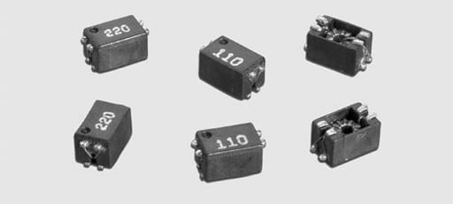
NiZn current-compensated SMD line filters (Würth Elektronik WE-SLM series)

At the same time, the leakage inductance is lower so the signal is less affected. The NiZn core current-compensated SMD line filters can therefore also be used at high signal frequencies.

MnZn Current-Compensated SMD Filter
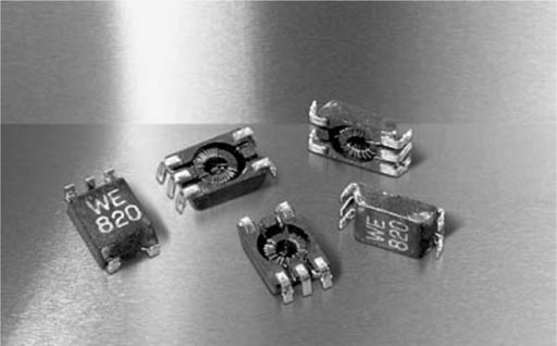
MnZn current-compensated SMD line filter (Würth Elektronik WE-SL1 series)

The MnZn current-compensated SMD line filter (such as Würth Elektronik WE-SL1 series) all excels by virtue of its low space requirement, both in terms of package height as well as footprint.

The manganese-zinc basic material provides adequate balances attenuation values.

MnZn Current-Compensated SMD Filter with Separated Construction
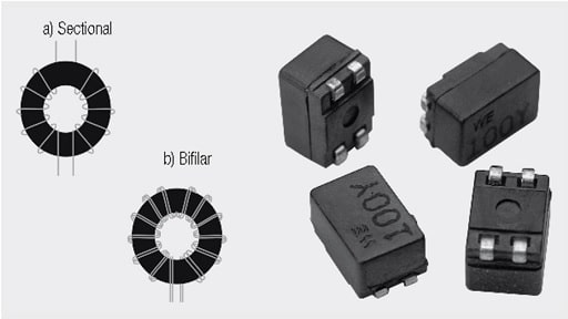
MnZn current-compensated SMD line filters with separated construction (Würth Elektronik WE-SL2 series)

The MnZn current-compensated SMD line filters can be prepared also with separated construction and both sectional and bifilar winding technology. 

The separated construction of the sectional winding allows both the attenuation of high frequency symmetrical frequency components, as well as the suppression of asymmetrical interference components. However, if the quality of the useful signal is too greatly affected, the original bifilar winding technology should be chosen.

High Density MnZn Current-Compensated SMD filter with Separated Construction
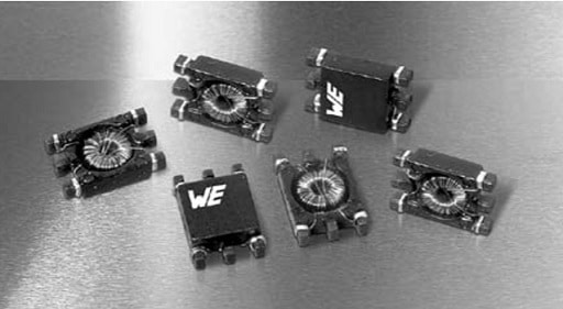
high density MnZn current-compensated SMD line filter with separated construction (Würth Elektronik WE-SL3 series)

The MnZn current-compensated SMD line filter with separated construction can be also made in high density version that represents an advancement of the MnZn current-compensated SMD line filters. Despite the halved package height, almost the same performance can be attained, at least for low inductance values. Additionally a 3x current-compensated version has been developed, which is mainly used for low voltages.

High Frequency MnZn Current-Compensated SMD Filter

A special high frequency design of manganese-zinc allows the frequency band in the single and double figure megahertz range to be covered.
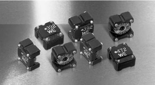
MnZn high frequency current compensated SMD filter (Würth Elektronik WE-SL3 series)

Current Compensated Choke for Mains Voltage Applications
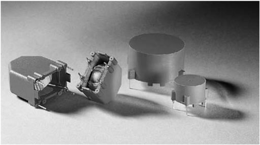
Mains voltage current compensated choke (Würth Elektronik WE-LF)
Mains voltage current compensated choke (Würth Elektronik WE-CMB)

Special construction of the current-compensated chokes allow the reduction of undesirable parasitic effects. Careful selection of core/winding relationship allows a very high current for a comparable footprint.

However, if conducting components or packaging parts are placed in the immediate vicinity, the required safety separation must be ensured on some types, as enameled wires are not considered to be insulated components. In most cases, the use of this design, however, unproblematic as insulated components, such as capacitors, provide the necessary separation.

Multi-chamber Current-Compensated Power Line Chokes
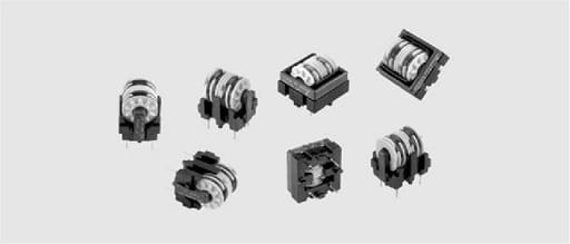
Multichamber current-compensated choke (Würth Elektronik WE-FC)

Multichamber current-compensated choke has roughly twice the leakage inductance relative to comparable toroidal chokes. The effect on symmetrical interference increases without having to use an additional inductor. Parasitic parallel capacitance is reduced as a result of the construction with a multi-chamber coil body.

The impedance profile is raised at higher frequencies. At the same time, resilience against burst and surge pulses is improved.

Attenuation Beads

A special variant of the toroidal inductor is the so called attenuation bead that becomes effective in the MHz range. It consists in its most simple form of a miniature toroid in low or high permeability ferrite or sometimes of iron powder. In alternative designs the “bead” becomes a tube or, depending on application, a double or multiaperture ferrite core. In all these variants the lead passes through the toroid. In designs where all space in the construction is consumed and we find afterwards that interference suppression measures are needed a small ferrite bead may be the solution.

It increases the inductance of the lead/wire in the RF range and functions as an energy absorber, for example, transients. A simple formula for
estimating the induction factor AL of the bead is Equation [1] below.

AL= µ x 0.4π/c » µ x 0.2 x h x ln(D/d) [1]

h is height, D is outer diameter, d is inner diameter of the toroid, The measures are expressed in mm.

Example: µ = 750, h = 2.5 mm, D = 6.3mm, d=3.8 mm gives AL = 750 x 0.2 x 2.5 x ln(6.3/3.8) = 190 nH.

Ferrite beads also are manufactured as chips. Examples of ferrite chip characteristics of two different materials are stated in the following table 1.
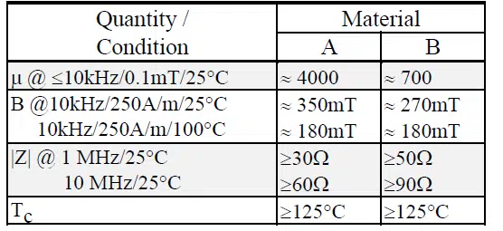
Table 1. Examples of ferrite chip material characteristics.

Note how the flux density B has been reduced considerably at 100 °C, though the Curie temperature TC is situated considerably higher.
How the different materials may depend on frequency is shown in following diagram.
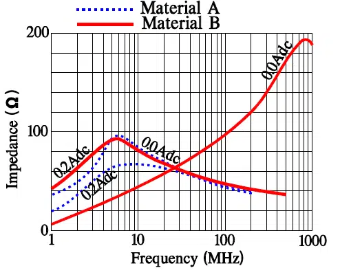
Figure 6. Examples of impedance versus frequency for several ferrite materials according to Table 1.

Note how lower permeabilities improve the impedance at higher frequencies as well as how DC load, increasing the flux density B, lowers the impedance. In order to cover a broader frequency band it might be necessary to connect in series ferrite beads with different materials.

Finally we should observe that ferrites have a certain conductance. In sensitive applications it might be necessary to use isolated/lacquered beads.

Furher Read

EMC Design Fundamentals: Safe Use of Varistors and Common Mode Chokes in Mains and Data-Line Filters


Related

Recent Posts

Bourns Introduces Automotive BMS Signal Transformer with Integrated Common Mode Chokes

17.7.2026
9

Bourns Introduces Automotive Shielded Power Inductors for Compact DC‑DC Converters

16.7.2026
30

EMC Design Fundamentals: Safe Use of Varistors and Common Mode Chokes in Mains and Data-Line Filters

16.7.2026
48

Square-Wave Harmonics and RMS Currents in Power Converters

14.7.2026
40

In the Age of AI, Every Watt Counts: Implications for Components

13.7.2026
60

RF Filters and Passive Components Enabling the 7 Missile RF Subsystems

9.7.2026
57

Ferrite versus Nanocrystalline Power Inductor Cores: Turns, Gap and Size

9.7.2026
86

YAGEO Presents NANOMET Soft Magnetic Cores for High‑Density Power Conversion

8.7.2026
141

Coilcraft Releases High-Current Ferrite Beads for CISPR 25 EMC compliance

8.7.2026
44

Upcoming Events

Jul 21
16:00 - 17:00 CEST

Safety by design: X and Y Interference suppression capacitors for power line filters

Jul 28
8:00 - 11:00 CEST

Post Procurement Testing of EEE Components for LEO Space Applications

Jul 29
17:30 - 18:30 CEST

To Ferrite or to Nanocrystalline in Transformer Design

View Calendar

Popular Posts

  • Boost Converter Design and Calculation

    0 shares
    Share 0 Tweet 0
  • Buck Converter Design and Calculation

    0 shares
    Share 0 Tweet 0
  • YAGEO Announces July 2026 Capacitor Price Increase

    0 shares
    Share 0 Tweet 0
  • Flyback Converter Design and Calculation

    0 shares
    Share 0 Tweet 0
  • LLC Resonant Converter Design and Calculation

    0 shares
    Share 0 Tweet 0
  • MLCC and Ceramic Capacitors

    0 shares
    Share 0 Tweet 0
  • Earthing Systems and IEC Classification Explained

    0 shares
    Share 0 Tweet 0
  • MLCCs in the Age of AI: Q2 2026 Market Tightness

    0 shares
    Share 0 Tweet 0
  • Nvidia Vera Rubin: Why One AI Rack Needs So Many More MLCC Capacitors

    0 shares
    Share 0 Tweet 0
  • Dual Active Bridge (DAB) Topology

    0 shares
    Share 0 Tweet 0

Newsletter Subscription


Passive Components Blog

© EPCI - Leading Passive Components Educational and Information Site

  • Home
  • Privacy Policy
  • EPCI Membership & Advertisement
  • About

No Result
View All Result
  • Home
  • Knowledge Blog
  • Dossiers
  • PCNS

© EPCI - Leading Passive Components Educational and Information Site

This website uses cookies. By continuing to use this website you are giving consent to cookies being used. Visit our Privacy and Cookie Policy.
Go to mobile version