


KEMET application note explains basic Battery Management System (BMS) function, topologies and inductor requirements. Metal composite inductor benefits for BMS and EMI suppression filter are benchmarked versus conventional ferrite core technology.
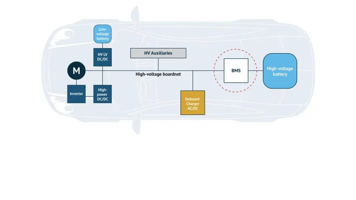
Battery Management System (BMS) is an indispensable part of electric vehicles. It is a vital link that connects on-board batteries and other electric vehicle parts such as the Vehicle Control Unit (VCU). Its main functions are described below. When one of the below functions fails, it will cause fatal harm to the battery. It could even cause the battery to explode or burn, causing accidents or casualties.
BMS Function, Topology and Structure Explained
Function of BMS
- Continuously monitor the condition of the battery unit (managing SOC, SOH, SOE, etc.)
- Prevent the battery cell from aging caused by repetitive operation of the battery. Examples include unbalanced cells caused by repeated charging or discharging, temperature changing, etc.
- Realize the long-term use of the battery pack and maximize the operating life
- Measure other parameters such as voltage and temperature of the whole battery pack or each battery cell
- Compensate for the slight inconsistency of each cell (balancing)
- Report the status and communicate with VCU or other ECUs
- Show the battery status on the car display unit and alert the driver if there are any abnormalities
BMS for Different Voltage and Capacity Levels
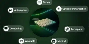
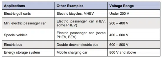
BMS is used in various battery-driven electronic devices, not only for automotive applications but also for a variety of non-automotive applications, from mobile phones to power storage devices. All automotive applications, from electric golf carts to EVs (the focus in this article will be on automotive applications highlighted in gray in the table below), need to use a BMS to ensure that the battery can operate safely. With different voltage and capacitance battery packs used in the products, some parts in the BMS need to be isolated.
Therefore, different topologies of BMS are required for the specific battery voltage and capacitance values. Table 1 shows some examples of applications that work at different voltage ranges.
Battery Type and Topology of Battery Pack
As a power battery for EV, many types of batteries can be used. Each battery has a different output voltage, safety, price, energy density, operation life, etc.
- Lead-acid battery
- Lithium-ion battery
- Nickel metal hydride battery
- Nickel cadmium battery
- All-solid-state battery
- Fuel cell
Among the above types of batteries, lithium-ion batteries are most commonly used in EVs because of their excellent energy density characteristics.
The battery pack most commonly used in EVs is when a single battery cell connects other single battery cells in series or parallel (usually in series) to form a battery module. It then combines the battery modules in series and parallel to create the final battery pack. For example, a battery pack labeled 330 V might be composed of 12 battery modules in series and 3 in parallel. Each battery module is composed of 12 battery cells in series. Assuming that the voltage of each lithium-ion battery cell is 2.3 V, the battery pack’s actual voltage will be 2.3 V x 12 x 12 = 331.2 V. More battery cells in series will increase the battery pack voltage, and more battery cells in parallel will increase the battery pack capacity.
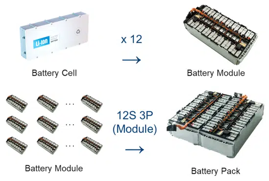
Battery Structure
A battery pack with a higher voltage or capacitance consists of more battery cells. In addition to the nominal voltage of the battery pack, we may also refer to the battery pack by the number of battery cells in series and parallel. With this concept, the battery pack in the example would be called a 144S (series) 3P (parallel) battery pack (S x P = the number of battery cells). The composition of the battery pack is shown in Figure 1.
Dispersion of BMS
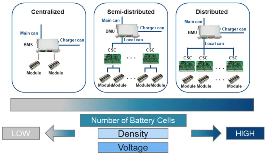
When the number of battery cells is small, the Battery Management Unit (BMU) and Cell Supervisory Circuit (CSC) are placed on the same PCB. But when the number of battery cells that need to be managed increases, the BMU and CSC, need to be placed on different PCBs. Each CSC has a limitation on the number of batteries that can be managed, and it helps reduce the total cable length. Therefore, the degree of dispersion depends on the number of battery cells that need to be managed (for hybrid vehicles, the higher the battery ratio, the larger the battery pack). The BMS products in the market can generally be divided into three different level topologies, which are shown in Figure 2. Their characteristics are discussed below.
Centralized BMS
Centralized BMS has the advantages of low cost, compact structure, and high reliability. It is common in small battery systems that they have lower capacitance and lower total voltage battery packs. Centralized BMS is generally used for low-speed vehicles such as electric bicycles, electric motorcycles, electric sightseeing cars, electric patrol cars, electric golf carts, etc., and also used for low battery/gasoline ratio hybrid vehicles as MHEV.
Semi-Distributed BMS
Semi-distributed BMS is between centralized and distributed BMS and manages a medium number of battery cells, with medium capacitance and voltage-rated battery packs. Like distributed BMS, its BMU and CSC are on different PCBs, but the number of battery modules managed by each CSC is more than one. Semi-distributed BMS can also be used in HEV, PHEV, and some EVs in electric vehicles.
Distributed BMS
Distributed BMS topology can better realize the hierarchical management of the module-level (module) module and the system-level (pack). As the power battery system of passenger cars continues to develop towards higher battery capacitance and higher voltage battery packs, the BMS with distributed topology is mainly used for PHEV and BEV. At present, mainstream mass-produced electric vehicles generally adopt a distributed BMS topology, especially for BEV.
Introduction to BMS and CSC
To achieve the BMS functions, the BMS will operate with two main parts, the main control board (referred to here as the BMU) and the slave board (referred to here as the CSC).
BMS also includes the part that manages high voltage called HVU, but it has been omitted because it is beyond the scope of this article.
The primary function of the BMU is to communicate with other ECUs/VCUs through CAN, process the data collected from CSC, and charge and discharge management. The CSC is responsible for voltage detection, temperature detection, balance management of the cells in the module (some have independent CSU module units), and corresponding diagnosis work.
If the CSC is directly connected to the battery module, CSC is on the high voltage side. So, the signal transmission between the BMU and CSC must be kept isolated typically, a pulse transformer or a capacitor is used as the isolation component) to separate the high voltage and low voltage sides.
Same as other applications, DC-DC is used for the power supply for main chips. Isolated DC-DC is used between high voltage and low voltage sides.
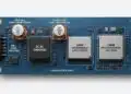
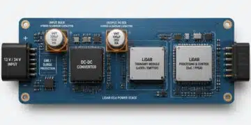
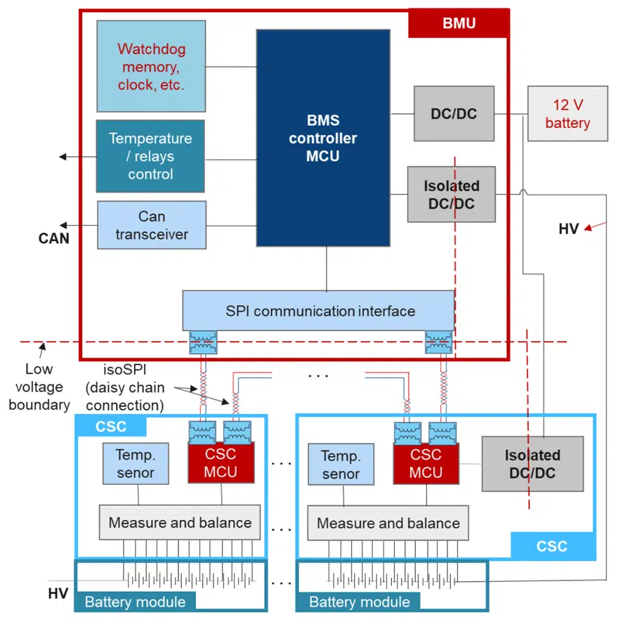
Figure 3 shows an example structure diagram of a distributed BMS.
Isolated and Non-Isolated DC/DC
It can be seen from Figure 3 that non-insulated DC/DC and insulated DC/DC are used in BMS. Usually, their operation is controlled by the DC/DC main chip. A power inductor needs to be used in a non-insulated DC/DC as a voltage transforming component in general solutions. Isolated DC/DC will use a transformer instead of an inductor as the voltage transforming component. Figures 4 and 5 shows isolated and non-isolated DC/DC circuit examples.
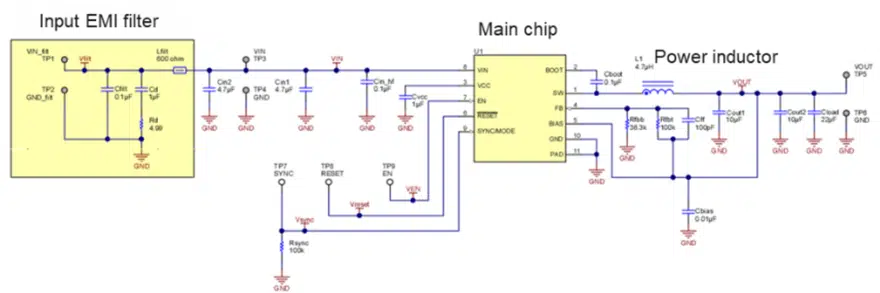
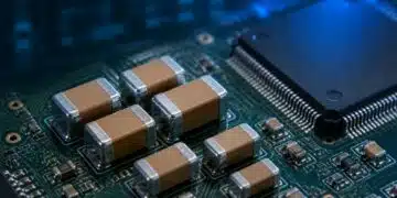
The main chip is the most critical component in the circuit, and it is the core of the circuit. Around the main chip, many passive components are used, such as resistors, capacitors, and inductors/transformers. Among 5 them, the inductor/transformer is an essential component. Its importance is next to the main chip in this circuit. The inductor/transformer is connected to the chip’s SW pin. Their function is to temporarily convert electrical energy into magnetic energy, store it in the magnetic core, and then release it in the form of electrical energy to transform voltage. Therefore, the quality directly affects the performance of the entire DC/DC circuit, such as efficiency, power losses, output ripple, EMI, response speed, etc.
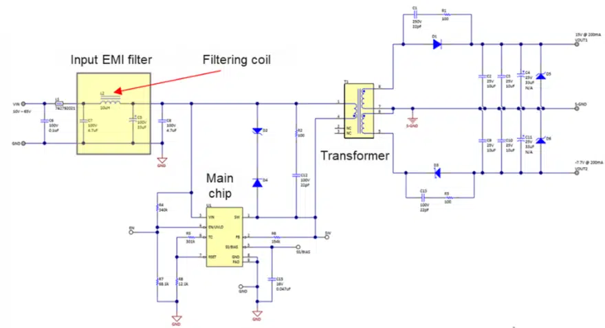
In addition, for applications with strict EMI requirements, EMI filters are used at the voltage input. EMI filters are usually made up of inductors, capacitors, and resistors individually or in multiple combinations, depending on the severity and frequency of EMI. The EMI filter of the non-isolated circuit in Figure 4 is mainly composed of two capacitors, and the EMI filter of the isolated DC/DC circuit in Figure 5 is primarily composed of two capacitors and an inductor. Since its shape looks like the symbol of π in mathematics, it is often called π Filter. The π-shaped filter has better filtering characteristics than the filter with only two capacitors in the non-isolated DC/DC circuit. Although EMI filtering is only an optional circuit, for BMS, which are required to work in harsh EMC environments, adding an EMI filter on the DC/DC circuit is highly advisable.
Inductor Selection
For the required inductors in the DC/DC of BMS, ferrite inductors and metal composite inductors (referred to here as METCOM inductors) are often used. In the past, because the number of batteries that needed to be managed was relatively small, the topology of the BMS was fairly simple. However, the trend for the number of batteries being managed is increasing. Therefore, the topology of the BMS becomes more complicated, increasing the number of chips such as MCU, memory, and communication chips. The result is that larger DC/DC output currents are required to maintain BMS operation.
On the other hand, the switching frequency of DC/DC chips is also developing to higher frequencies. As a result, the ferrite inductor commonly used in DC/DC circuits is now superseded by METCOM materials. There are three main reasons.
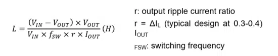
Required L Value Decreases and Output Current Increases
From a synchronous buck DC/DC (Equation 1), one can see that the inductance value needed in DC/DC is inversely proportional to the switching frequency (FSW) and output current (IOUT).

In comparing the characteristics of ferrite inductors and METCOM inductors in Table 2, there is a trade-off of inductance value and rated current between ferrite and metal composite material. This tradeoff means that the requirement for the inductance value decreases as BMS topology gets more complicated with chip developments. The reduced inductance required by the DC/DC means that METCOM has more opportunities to be used and replace ferrite inductors in exchange for other benefits of the metal composite material. Examples include soft saturation characteristics and EMI characteristics (explained in the following sections).
Soft Saturation Characteristics of METCOM
When the current flowing through the inductor increases, the inductor will tend to magnetically saturate its core due to the magnetic field generated by itself. As the degree of magnetic saturation increases, the inductance value will drop. If the current continues to increase, the inductance value of the inductor will eventually fall to near 0, which is called the inductor’s DC superposed characteristics. Compared with ferrite inductors, METCOM inductance drop caused by DC superimposition characteristics is relatively stable (see Figure 6).
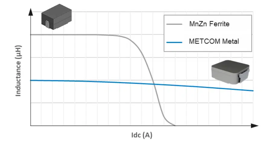
If circulating currents suddenly increase from the normal value (preset value) due to a malfunction or the like, METCOM inductance remains more stable than older ferrite inductors. Since the decrease in inductance caused by the DC superimposition characteristics is synchronized with the increase in current, even if the current increases for a short period, the inductance value will fall instantaneously. From the calculation of ripple current (Equation 2), one can see that a decrease in the inductance value will increase the output ripple current of the DC/DC circuit. In extreme cases, that inductance drop will cause the current to run out of control, and in the worst case, it may even cause the burning of the chip or other components. Therefore, the DC superimposition characteristics are an important indicator when choosing an inductor for BMS DC/DC.

EMI Characteristics
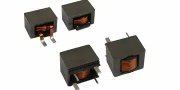
Due to the limitation of the production process of ferrite inductors, it can only be produced in an assembled manner, as shown in Figure 7. Therefore, there must be gaps between each section, and these gaps will cause magnetic leakage problems and worsen EMI. Some ferrite inductors will add a shielding cover on the periphery. Although this can make some improvements, it can never form a “closed magnetic circuit.”
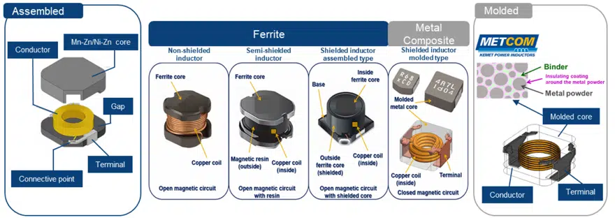
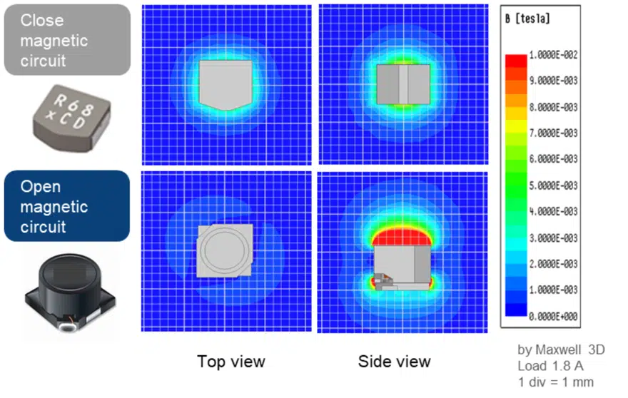
As a result, there will still be a certain amount of magnetic leakage. METCOM is a one-piece molding with metal composite powder mixed with a binder and formed in the mold so that the inductor forms a” closed magnetic circuit,” which can significantly reduce the leakage of magnetic field and reduce the impact of EMI (see Figure 8). A harsh EMI environment may interfere with BMS data communications or lead to a progressive decline in quality.
Wireless Solutions and FLEX SUPPRESSOR
At present, the primary function of BMS is to connect the BMU and CSC in a wired solution for communication between BMU and CSC. As mentioned above, it is generally connected in a daisy chain way in the IsoSPI protocol using twisted pair cables. However, when the number of battery modules increases, too many cables may cause problems such as complicated wiring and overall weight. On the other hand, because IsoSPI requires strict isolation between different modules, the number of isolation components also needs to increase, resulting in a more complicated circuit design. Therefore, there is a new solution to replace the traditional wired solution by using wireless transmission instead. In hardware, a wireless solution needs to add a wireless chip (usually 2.4 GHz Bluetooth standard) to each SCS and BMU board instead of using the signal line for communication. Their circuit diagram is shown in Figure 9.
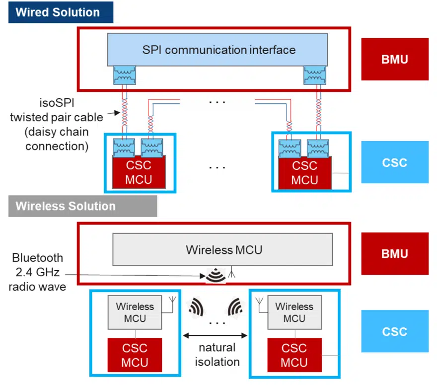
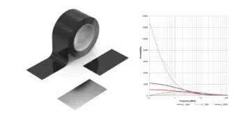
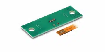
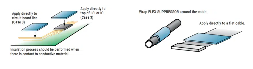
Because the wireless solution has natural isolation between board and board, it can reduce the isolation components and cables compared with the wired method. Although the wireless solution solved the problem caused by too many cables and isolation components, it is necessary to overcome the internal interference problem caused by the complex EMI environment in BMS that decreases antenna sensitivity. In addition to using more filter components in the circuit to reduce the noise generated by the circuit board itself, the use of an electromagnetic shielding case and electromagnetic absorbers will also help suppress the noise to keep the antennas in a good sensitivity state. KEMET’s FLEX SUPPRESSOR is a kind of magnetic absorber sheet. By attaching this to the interference noise source on the circuit board or the noise transmission path can effectively suppress the noise that interferes with Bluetooth operating in a 2.4 GHz frequency band. Figure 10 shows examples of how these NSS products (Noise Suppression Sheet) or NST (Noise Suppression Tape) can be applied.
Conclusion
- The topology of BMS tends to become more complicated due to the increase in the number of battery cells that need to be managed.
- The rise in the number of various chips used in BMS requires the DC/DC converter to provide more power, resulting in the output current of DC/DC increasing.
- Since the BMS is often needed to work in complicated EMI environments, the EMI susceptibility of the BMS becomes critical to the safety of the system. For this reason, careful attention must be given to EMC.
- If the BMS fails, there is a chance that it will lead to severe and fatal consequences, so the components used in the BMS must have high reliability.
- As the switching frequency of the DC/DC converter increases, the required L value of the inductor decreases, and the rated current of the inductor must increase. Metal composite METCOM inductors, therefore, becomes the primary inductor technology for this application.
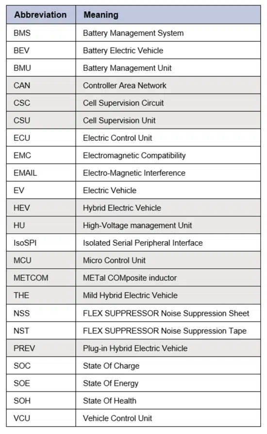
List of Abbreviations