


This article explains some basic parameters of capacitors – insulation resistance and DCL leakage current.
Key Takeaways
- Capacitors have insulation resistance (IR) and DC leakage current (DCL) that measure their ability to retain charge.
- Electrostatic capacitors usually demonstrate IR, while electrolytic capacitors show DCL; both parameters are crucial for performance.
- Leakage current varies with capacitor type, voltage, and temperature, impacting applications like power supplies and amplifiers.
- Capacitors’ DCL and IR are related mathematically; increased temperature or voltage boosts leakage current significantly.
- Myths suggest that high leakage current indicates low reliability, but actual reliability depends on capacitor construction and design.
Important feature of capacitor apart its capacitance is:
- its ability to keep the charge for some time without self-discharging due to its internal leakage (conductivity) mechanisms. This is characterized by either IR Insulation Resistance or DCL leakage current electrical parameters. These are reciprocal parameters describing the same capacitor stage, so it does not matter which of those parameters is used. Electrostatic capacitors such as paper, organic film or ceramic capacitors are usually characterized by IR values, while electrolytic capacitors (aluminum, tantalum) with low IR values are using DCL leakage current specification instead.
- withstand a voltage before it breakdown. This is defined by its maximum Operating Rated Voltage and Breakdown Voltage. Rated voltage is a common parameter that you can find in catalogues and it practically means that manufacture guarantee the specified electrical parameters and reliability are maintained up to this voltage. The maximum rated voltage can be categorized by AC/DC operation or maximum allowed operating temperature (so called Category Voltage – will discuss this in next lectures).
Basic Charge Storage and Discharge
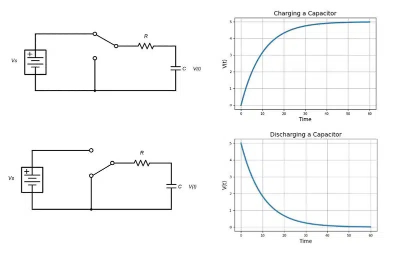
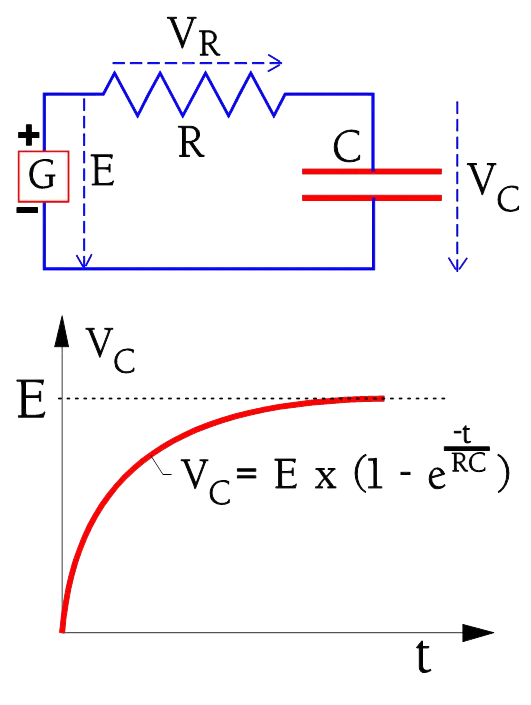
When connected to a direct current (DC) voltage source, capacitors charge almost instantaneously, but they can discharge just as fast if shorted; however, with some resistance in place, the rate of charge and discharge is exponential rather than direct (Figure 1.).
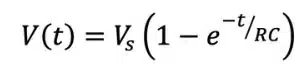
The charging formula is expressed as:
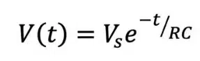
The discharging formula is expressed as:
Oscillators, waveform shapers and low-discharge power backup circuits are examples of electronics that leverage controlled charge and discharge rates.
Insulation Resistance IR and Leakage Current DCL

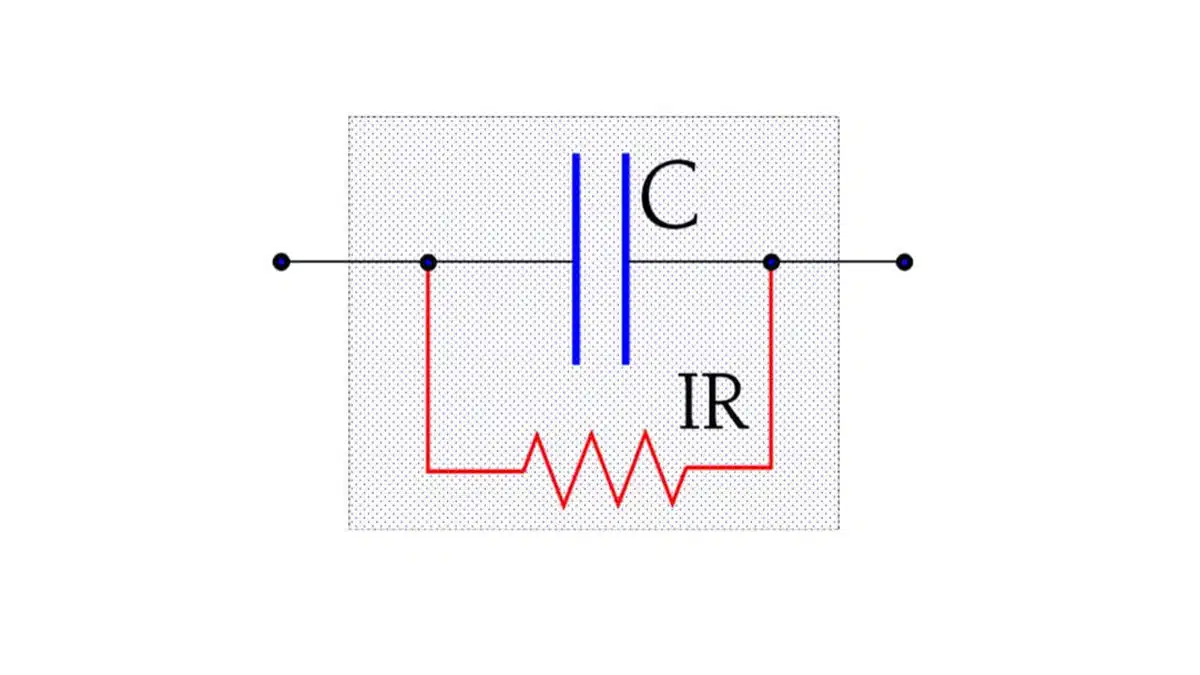
The dielectric of a capacitor has a large area and a short length. Even if the material is a good isolator there always flows a certain current between the charged electrodes (the current increases exponentially with the temperature). This leakage can be described as a parallel resistance with a high value, an Insulation Resistance (Figure 2.). We use the abbreviation IR in the following.
Measurement of the IR and Leakage Current
At an IR determination one measures the DC leakage current through the capacitor. The measuring circuit, however, always contains a certain series resistance.
Hence we need take into consideration the charging time. The circuit diagram and charging curve for a capacitor are shown in Figure 3.
The charging current to the capacitor is shown in Figure 4. (circuit diagram as in Figure 3.). If the capacitor is ideal the current would rapidly attain the limiting value corresponding to the IR. The ideal current curve is designated IC-ideal. But because the polarization in the dielectric requires a finite time for dipoles to reorient the real charging current follows the curve IC-polarization.

In order to attain the actual IR we would need to wait for a very long time. In practice we content ourselves with a specified IR value corresponding to a measuring current at the time tmeasure in Figure 5. Here we have marked a specified current value which on the measuring devices are graded in the corresponding IR value. A common time for IR readings is in IEC specifications 1 minute. The MIL specifications often call for 2 minutes or more. Considerably shorter times are applied at incoming and production inspections. Information in this book is based on the 1 minute value if nothing else is stated. Additionally the IR concerns the ”room temperature condition” (RT), approximately 23 °C. The IR decreases with an increase in part temperature and may, at the maximum temperature, be several 10 powers lower than at RT.

The IR of capacitors of a specific type and voltage rating decreases proportionally to the growth in capacitance (i.e., the increasing area). And vice versa. A reduced capacitance by a correspondingly lessened area will increase the IR. However, up to a specific maximum value of capacitance the IR actually is so high that it’s actually the outer construction and the molding or conformal coating that determines measured values. Up to this point one specifies the IR in M. Above this breakpoint the specifications call for the constant product of IR x C (in seconds). This product also is designated the time constant (see next section).
For electrolytic capacitors with their relatively low IR rather the leakage current is specified.
See also follow up article with more details on Leakage Current Characteristics of Capacitors
The time constant
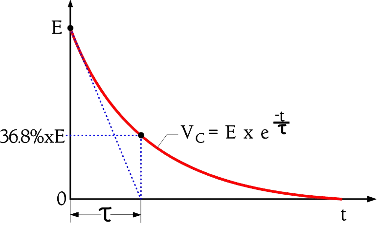
If we leave a charged capacitor with open connections the charge successively will leak from one electrode to the other through the internal insulation resistance. Eventually the voltage will drop to zero. Because of the very high IR of the electrostatic capacitor (non electrolytic) a complete discharging will take an extremely long time. A more comprehensible measure of the discharge speed is the time constant. It is defined as the time for the initial voltage E to drop to the value 1/e by E (Figure 6.). With reference to Figure 2. and figure 3. we can define as the product IR x C. This quantity is deduced as Ω x As/V = Vs/V = s(econds). Periodically one sees the expression ohm-farad (ΩF) or the somewhat awkward megohm-microfarads (MΩF). Instead of using the expression IR x C it’s customary to mention only the RC product of the capacitor. Then R is understood as IR, i.e. IR x C = RC = τ .
τ = RC (s) or (ΩF) ………….[1]
Capacitors, just like other electronic components, are constructed with imperfect materials. The imperfections and defects in these materials have significant effects on the electrical performance of capacitors. Some of the parameters determined by these defects and imperfections include impedance, dissipation factor, inductive reactance, equivalent series resistance, and leakage current. When designing an electronic circuit, it is necessary to consider leakage current characteristics of capacitors.
DC leakage current is one of the key characteristics to consider when selecting a capacitor for your design. Other important parameters include working voltage, nominal capacitance, polarization, tolerance, and working temperature. Basic leakage current definitions and its reciprocal value – insulation resistance can be found in the following article here.
Leakage current and its effects on the performance of capacitors
The conductive plates of a capacitor are separated by a dielectric material. This material does not provide perfect insulation, and allows current to leak through it. The DC leakage current refers to this small current that flows through a capacitor when voltage is applied. The value of this current mainly depends on applied voltage, capacitor temperature, and charging period.
The amount of leakage current varies from one type of capacitor to another, depending on the characteristics of the dielectric material and construction. Aluminium electrolytic capacitors have a large leakage current while ceramic, foil, and plastic film capacitors have small leakage currents. A very small leakage current is commonly referred to as “insulation resistance”.
In electronic circuits, capacitors are used for a wide range of applications including decoupling, filtering, and coupling applications. Some applications such as power supply systems and amplifier coupling systems demand capacitors with low leakage currents. Aluminium electrolytic capacitors and tantalum capacitors have high leakage currents and are generally unsuitable for such applications. Plastic and ceramic capacitors have lower leakage currents, and are commonly used for coupling and storage applications.
Leakage Current vs. Insulation Resistance
The dielectric materials used in capacitors are not ideal insulators. A small DC current can flow, or “leak” through the dielectric material for various reasons specific to each dielectric. As a result, when a capacitor is charged to a certain voltage, it will slowly lose its charge. As it loses its charge, the voltage between the capacitor’s electrodes will drop.
The leakage current (DCL) and the insulation resistance (IR) are in simple mathematical relation to each other:
R (IR) = V / I (DCL) or I (DCL) = V / R (IR)
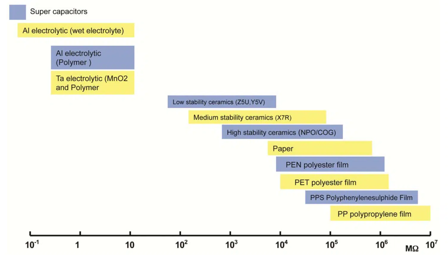
Since the values are related, the usage of the terms leakage current and insulation resistance will vary depending on the dielectric type. Aluminum electrolytic capacitors have a relatively large leakage which is thus referred to as leakage current. Alternatively, plastic film or ceramic capacitors have a very small leakage current, so the effect is quantified as an insulation resistance. See figure 7. overview of IR on most common capacitor dielectric types.
Generally, insulation resistance tends to decrease with higher values of capacitance. For practical reasons the insulation resistance may be expressed in Megaohms at low capacitance values, and in Ohm-Farads (equals seconds) at higher capacitances. The Ohm-Farad expression allows a single figure to be used to describe the insulation performance of a given component family over a wide range of capacitance values. The leakage current is also dependent on the temperature. As the temperature increases, so does the leakage current.
DCL leakage currents in electrolytic capacitors is also mentioned in the article here.
Dependence of leakage current on time
Charge/Discharge Behavior
When a DC voltage is applied to a capacitor connected in series with a resistor, the capacitor begins to charge at a rate according to the applied voltage, the state of charge relative to its final value, the series resistance, and its own capacitance. The product of the resistance and capacitance is referred to as the time constant (I = R x C) of the circuit. Actually, it is the time required to charge the capacitor by 63.2% of the difference between the initial value and the final value. Hence, the value of charge plotted against time follows the curve shown in Figure 8. During this time, the charging current follows the red curve also shown in Figure 8.
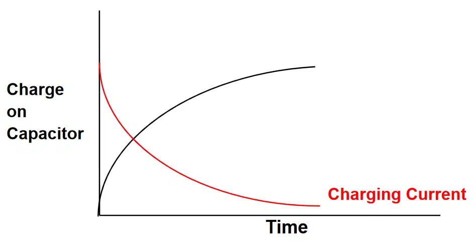
The charge on the capacitor at any time, t, is calculated by the following equation:
Q = C x V x [1 – e-t/RC]
The charging current decays according to the equation:
I = V/R x e-t/RC
Where e = 2.7182818, the so-called “natural number,” or the base of natural logarithm, ln(x).
The leakage currents of some capacitors are dependent on time. At the instant the voltage is applied to a capacitor, the current is at its peak. The occurrence of this peak current depends on construction of the capacitor. In the case of aluminum electrolytic capacitor it is the forming characteristics of a capacitor and the internal resistance of the source of voltage. When a capacitor is charged, its leakage current drops with time to a nearly constant value called operational leakage current. This small leakage current is dependent on both temperature and applied voltage.
Some capacitor technologies such as aluminium, tantalum and film capacitors have self-healing properties. The self-healing process may have a significant effect on the leakage currents of the capacitors while the exact mechanisms may be specific to the capacitor technology type. Time dependence of leakage currents is also caused by dielectric material type and its structure. Other parameters that determine the value of this small current include the type of electrolyte, capacitance, and forming voltage of the anode. The leakage current of a ceramic capacitor does not change with time.
Dependence of leakage current on temperature
The leakage current of a capacitor is dependent on temperature. The level of dependency varies from one type of capacitors to another. For aluminium electrolytic capacitor, an increase in temperature speeds up the rate of chemical reaction. This results in an increase in leakage current.
Compared to ceramic capacitors, tantalum capacitors have high leakage currents. The DC leakage current of a tantalum capacitor increases with an increase in temperature. The leakage currents of tantalum capacitors increase slightly when they are stored in a high temperature environment. This small increase in leakage current is temporary, and it is reversed by applying rated voltage for a few minutes. In addition, the leakage current of a tantalum capacitor increases slightly when the component is exposed to high humidity. Voltage conditioning helps to reverse this temporary increase in leakage current.
Ceramic and film capacitors have small leakage currents relative to electrolytic capacitors. For multilayer ceramic capacitors (MLCCs), the intrinsic leakage currents increase exponentially with an increase in temperature. The insulation resistance of a film capacitor is determined by the properties of the dielectric material. For this type of capacitor, an increase in temperature causes a decrease in insulation resistance and an increase in leakage current.
Dependence of leakage current on voltage
The DC leakage current of a capacitor is greatly dependent on the applied voltage. For aluminium electrolytic capacitors, this current increases with an increase in operating voltage. As the operating voltage exceeds the rated voltage and approaches the forming voltage, the leakage current increases exponentially. When the voltage applied to an aluminium electrolytic capacitor exceeds the surge voltage, the tendency towards temperature rise, electrolyte degradation, formation of excess gas, and other secondary reactions increases. Due to this reason, operating an aluminium electrolytic capacitor beyond the rated voltage is not tolerable. The DC leakage current of an aluminium electrolytic capacitor drops sharply when the applied voltage is decreased below the rated voltage.
The leakage current of an aluminium electrolytic capacitor increases when the component is stored for a long period of time. Such capacitors are restored to original characteristics through reconditioning. The process involves applying rated voltage to the capacitor for about half an hour.
For ceramic capacitors, the intrinsic leakage currents are greatly dependent on voltage. An increase in voltage results in a superlinear increase in intrinsic leakage current. The insulation resistance of a ceramic capacitor is independent of voltage.
DCL Myths
There are some common myths related to DCL leakage current of capacitors that can be heard still today:
Myth 1: IR/DCL leakage current is due to the cracks in dielectric.
This was one of the first imagination theory of why dielectrics have a leakage current without a details understanding of the physical mechanisms inside the insulators. It is true that cracks and “imperfections” in dielectric structure can be a cause of leakage current increase and catastrophic failures on individual “faulty” components. On the other hand, it may not be the prime issue for the basic leakage current level – we have to understand the physical conductivity mechanisms that takes place at the specific capacitor technology dielectric.
The details conductivity mechanisms description is beyond this lecture focus, but lets simplify it that in a capacitor the conductivity through the dielectric can be composed of three major mechanisms (all three are typical for electrolytic capacitors):
- Ohmic conductivity
- Poole Frankel mechanism – It can be imagined as electron or holes “hopping” through a traps in the dielectric inner volume
- Tunneling mechanism – this is a dangerous zone that should happen above the operational voltage. Under high electric field intensity electrons/holes are accelerated to cross all the barriers with risk of avalanche effect and catastrophic breakdown of the part resulting in short circuit. So we can assume this as the main electrical breakdown mechanism
Another big influence to the value of DCL is the construction of the capacitor itself – namely the electrical potential between the electrode systems and the insulating dielectric. Metal electrodes may have some sub-oxide layers that are semiconducting and also electrolyte in electrolytic capacitors may exhibit rather semiconducting behavior – so in-fact in many cases on capacitors we are not faced with a simple Metal-Insulator-Metal structures, but more complex Metal-Insulator-Semiconductor systems, where interface barriers may play the leading role to the overall DCL leakage current values.
Myth 2: IR/DCL leakage current is a measure of the component reliability
This common myth is actually related to the Myth 1 as the imagination was that the part with higher leakage current has also larger number of cracks and thus it presents higher reliability risk.
As we learned in the Myth 1 mitigation above, the actual leakage current of a “standard” capacitor is due to its dielectric conductivity mechanisms and construction (electrical potentials matching). DCL of statistically normally produced capacitors is not a measure of reliability and it was confirmed many times that screening of DCL tail distribution is not improving the basic reliability numbers.
HOWEVER, Change of DCL as the structure robustness to external load can be a measure of reliability. There are number of proved screening methods that are part of specifications (MIL,ESA) or applied internally by manufactures as their know-how where a certain (thermo)mechanical and electrical stress is applied with subsequent DCL screening to improve reliability level and sort-out suspicious parts.
Case study: It was quite common to hear that leakage current on tantalum solid electrolytic capacitors with MnO2 electrode is due to the cracks in dielectrics. When conductive polymer electrode was developed, it replaced MnO2 solid electrolyte but DCL increased in 10fold time. This raise natural questions: Why DCL increased when the dielectric is identical and we exchanged electrolyte material only ? Does it mean that polymer type reliability is ten time worse? … of course, it is not true, the answer is that we replace one semiconducting electrolyte to the other and influenced the electrical barriers that are “more open” now and it drains more electrons/holes through it. But this is a natural stage of the capacitor construction without a direct impact to its reliability. How many times I still hear today that cracks are the main cause of leakage current in capacitors … It is cited in literature and still copied and pasted by many authors without any deeper insight.
FAQ about Capacitors Insulation Resistance and Leakage Current
Insulation resistance (IR) is the measure of how well a capacitor’s dielectric prevents current leakage between its electrodes. A higher IR means better insulation and lower leakage. Electrostatic capacitors (ceramic, film) are usually specified by IR values.
DC leakage current (DCL) is the small current that flows through a capacitor’s dielectric when voltage is applied. It is the reciprocal of insulation resistance. Electrolytic capacitors (aluminum, tantalum) are typically specified by DCL instead of IR.
They are mathematically reciprocal: R(IR) = V / I(DCL). A high insulation resistance corresponds to a low leakage current, and vice versa.
Leakage current depends on applied voltage, temperature, dielectric type, capacitance, and time. Higher temperature and voltage generally increase leakage current.
Applications such as power supplies, coupling circuits, and amplifiers require capacitors with low leakage currents to ensure efficiency and stability. Ceramic and film capacitors are preferred for low-leakage needs.
How to Measure Insulation Resistance and Leakage Current of a Capacitor
- Prepare the test setup
Connect the capacitor to a DC voltage source with a series resistor to limit current. Ensure the capacitor is discharged before testing.
- Apply the rated voltage
Apply the capacitor’s rated DC voltage and allow it to charge. The charging current will initially spike and then decay exponentially.
- Wait for stabilization
Allow sufficient time (commonly 1 minute per IEC standards, 2 minutes for MIL standards) for polarization effects to settle.
- Measure leakage current
Record the steady-state current flowing through the capacitor. This is the DC leakage current (DCL).
- Calculate insulation resistance
Use the formula IR = V / I, where V is the applied voltage and I is the measured leakage current. This gives the insulation resistance in ohms.
- Interpret results
Compare the measured IR or DCL with the capacitor’s datasheet specifications. A significantly lower IR or higher DCL may indicate degradation or defects.


