• Latest
  • Trending
  • All
  • Capacitors
  • Resistors
  • Inductors
  • Filters
  • Fuses
  • Non-linear Passives
  • Applications
  • Integrated Passives
  • Oscillators
  • Passive Sensors
  • New Technologies
  • Aerospace & Defence
  • Automotive
  • Industrial
  • Market & Supply Chain
  • Medical
  • RF & Microwave
  • Telecommunication

Comparison of Chip Capacitors and Chip Varistors in Electrostatic Countermeasures

3.11.2016

Flex Suppressor Explained and its Applications

24.3.2023

Exploring the Benefits of High-Performance MLCC Capacitors for Aerospace and Defense

23.3.2023

Murata Establishes Joint Venture Company to Produce MLCC Raw Materials

23.3.2023

Examining the Influence of ESR and Ripple Current on Selecting the Suitable Capacitor

21.3.2023

SABIC Validates its 150°C Film Foil to Enable Adoption of Film Capacitors in SIC Power Modules

20.3.2023

Outlook of Passive Electronic Components Market for Oil & Gas Electronics in 2023

20.3.2023
  • Home
  • Privacy Policy
  • EPCI Membership & Advertisement
  • About
No Result
View All Result
NEWSLETTER
Passive Components Blog
  • Home
  • NewsFilter
    • All
    • Aerospace & Defence
    • Antenna
    • Applications
    • Automotive
    • Capacitors
    • Circuit Protection Devices
    • Filters
    • Fuses
    • Inductors
    • Industrial
    • Integrated Passives
    • Market & Supply Chain
    • Medical
    • New Materials & Supply
    • New Technologies
    • Non-linear Passives
    • Oscillators
    • Passive Sensors
    • Resistors
    • RF & Microwave
    • Telecommunication

    Flex Suppressor Explained and its Applications

    Exploring the Benefits of High-Performance MLCC Capacitors for Aerospace and Defense

    Murata Establishes Joint Venture Company to Produce MLCC Raw Materials

    Examining the Influence of ESR and Ripple Current on Selecting the Suitable Capacitor

    SABIC Validates its 150°C Film Foil to Enable Adoption of Film Capacitors in SIC Power Modules

    Outlook of Passive Electronic Components Market for Oil & Gas Electronics in 2023

    Flying Capacitors Explained

    TDK Introduces Compact High-Current Chokes for Automotive and Industrial Applications

    ECIA NA February 2023 Electronic Components Sales Confirms Growth Trend

    Trending Tags

    • Ripple Current
    • RF
    • Leakage Current
    • Tantalum vs Ceramic
    • Snubber
    • Low ESR
    • Feedthrough
    • Derating
    • Dielectric Constant
    • New Products
    • Market Reports
  • VideoFilter
    • All
    • Antenna videos
    • Capacitor videos
    • Filter videos
    • Fuse videos
    • Inductor videos
    • Non-linear passives videos
    • Oscillator videos
    • Passive sensors videos
    • Resistor videos
    • Sensors

    Investigating Modeling Techniques of Class II Ceramic Capacitors Losses for High Voltage and Current Applications

    Understanding Basics of Current Sense Resistors

    What Decoupling Capacitor Value To Use And Where To Place Them

    How to Measure Rated Current on Power Inductors

    LTspice Simulation of a Spark-Gap Circuit Protection Surge Arrester

    Approximate Inductor Design Using Two Alternative Cores

    1kW Phase Shift Full Bridge Converter Design and Simulation

    Multiphase Buck Trans-Inductor Voltage Regulator (TLVR) Explained

    Smart Power Distribution Unit Architecture and Inductor Losses

    Trending Tags

    • Capacitors explained
    • Inductors explained
    • Resistors explained
    • Filters explained
    • Application Video Guidelines
    • EMC
    • New Products
    • Ripple Current
    • Simulation
    • Tantalum vs Ceramic
  • Knowledge Blog
  • Suppliers
    • Preferred Suppliers
    • Who is Who
  • Events
No Result
View All Result
Passive Components Blog
No Result
View All Result

Comparison of Chip Capacitors and Chip Varistors in Electrostatic Countermeasures

3.11.2016
Reading Time: 10 mins read
0 0
0
SHARES
211
VIEWS

source: TDK application note

Recently released TDK application note compare chip capacitor and chip varistor ESD performance.

RelatedPosts

Flex Suppressor Explained and its Applications

Exploring the Benefits of High-Performance MLCC Capacitors for Aerospace and Defense

Murata Establishes Joint Venture Company to Produce MLCC Raw Materials

Electrostatic Countermeasure By Multilayer Ceramic Chip Capacitors
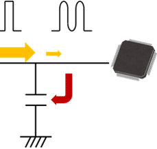
Protection components are used as an electrostatic countermeasure in equipment. Protection components are placed in circuits to protect ICs or electronic components, and to protect ICs or peripheral electronic components from static electricity that generate from places such as switches or headphone jacks. Protection components are largely divided into four categories: Zener diodes (TVS diodes), multilayer chip varistors (MLVs), ESD suppressors, and multilayer ceramic chip capacitors (MLCCs). When there is no limit for inserted capacitance, MLCCs are often used.
Since the electrostatic absorption capacity of a MLCC becomes greater as the capacitance becomes larger, components with a larger capacitance are selected. However, if changes such as switching to an IC with a faster communication speed are made due to a design change by the end user. The signal waveform may be distorted due to the effect of large capacitance (Fig. 1). If the MLCC is switched to one with smaller capacity so as to improve this, electrostatic countermeasure may become insufficient. In such a case, it is necessary to choose protection components other than MLCCs.
This material describes the characteristics of each protection component, as well as the differences between an MLCC and MLV.

Communication speed: Low                                                                      Communication speed: High

Fig. 1 Signal waveform distortion due to difference in communication speed

Characteristics of Each Protection Component Used as ESD Countermeasures
In order to protect semiconductor devices or circuits from surges including ESD, protection components such as multilayer ceramic chip capacitors, ESD suppressors, TVS diodes, and MLVs are used. The characteristics of these protection components are summarized below (Table 1).

Table 1 Features of each protection component

 
Type L x W size Capacitance(pF) Features
1 or lower 1 to 50 50 to 100 100 or higher
MLV 0.4mm x 0.2mm
[EIA01005] or larger
✓ ✓ ✓
  • Available in 0.4mm x 0.2mm [EIA 01005] and features a broad capacitance range
  • Internal resistance change (nonlinear characteristic) of the component is caused by voltage application, which suppresses ESD.
  • Internal resistance change (nonlinear characteristic) of the component is caused by applying voltage, such as ESD.
TVS diode 0.6mm x 0.3mm
[EIA0201] or larger
✓ ✓ ✓
  • Bottom terminals/side terminals
  • Internal resistance change (nonlinear characteristic) of the component is caused by applying voltage such as ESD.
  • The internal resistance of the component decreases in response to ESD, bypassing it to the GND.
ESD suppressor 0.6mm x 0.3mm
[EIA0201] or larger
✓
  • Low capacitance:0.05pF
  • When the applied voltage exceeds the trigger voltage of the component, a gap discharge occurs in the component and suppresses ESD.
MLCC
(for ESD Protection)
1.6mm x 0.8mm
[EIA0603] or larger
✓
  • Features a broad capacitance range
  • Charges the discharge current of ESD in the capacitance.
                a. No protection component                                                    b. ESD suppressor
                         c. MLCC (0.1μF)                                                                   d. TVS diode
e. MLV (AVR-M0603 type)
    
Fig. 2 ESD waveform (ESD absorption waveform) in a circuit incorporating each ESD protection element
Fig. 2 shows the ESD absorption waveform when each protection component is used. Based on IEC61000-4-2, an ESD waveform was generated using an HBM (Human Body Model) and the electrostatic absorption capability of each protection components was evaluated. The horizontal axis represents time (ns), and the vertical axis represents voltage (V). This voltage is considered to be the voltage that is applied to the IC when static electricity is generated, and the smaller the voltage, the higher the protection capability from static electricity.
  • When no protection component is used (ESD simulator charge voltage 8 kV, 150 pF, 330Ω, contact discharge), the pulse surge shows a waveform in which the voltage value gradually decreases after a steep rise of the initial peak voltage. The peak voltage (Vpeak) reaches as high as 1,500 V, and the average voltage (Vave) between 30 ns and 100 ns is also as high as 400 V.
  • An ESD suppressor is a type of protection component that forms a short circuit at a specified voltage when the applied voltage is gradually increased, and suddenly allows the current to flow. This voltage is called the trigger voltage. Although an ESD suppressor can suppress Vave to 29 V, it can only suppress Vpeak to approximately 500 V due to the high trigger voltage.
  • An MLCC suppresses voltage by charging the ESD electric charge with its capacitance component. Therefore, the larger the capacitance, the greater the ESD suppression capability. An MLCC is capable of suppressing Vpeak to approximately 23 V. However, since it later discharges accumulated charges, a large voltage peak will be generated a several hundred nanoseconds later.
  • A TVS diode is a protection component derived from a Zener diode (constant voltage diode) used for ESD countermeasure. It is also called a transient voltage suppressor. Its ESD absorption waveform shows excellent properties, with low Vpeak and Vave.
  • An MLV also shows a waveform having low Vpeak and Vave, as in the case of a TVS diode. In addition, since an MLV has a capacitance component, it has an advantage over a TVS diode in suppressing Vpeak. However, in MLVs, the ESD suppression capability tends to become worse as the capacitance becomes larger; therefore, in high-speed signal circuits in which large capacitance cannot be inserted, TVS diodes show superior properties.


Fig. 3 shows a map of the best-suited protection component for each application. The horizontal axis represents the signal speed, and the vertical axis represents the electrostatic absorption performance. In addition, the communication speed of each standard is shown in the lower part. Using this graph, the best suited protection component can be selected for each standard. MLCCs can be used in signal lines with a signal speed of 1Mbps or less. In signal lines with higher speeds, chip varistors, TVS diodes, or ESD suppressors are suitable. As is indicated by Fig. 3, there are AVRM series and AVRL series chip varistors of TDK. The AVRM series features high capacitance and high electrostatic absorption capability, realizing electrostatic absorption in signal lines with speeds from 10kbps to 100Mbps. On the other hand, the AVRL series features low capacitance, and exhibits a higher electrostatic absorption capacity than that of ESD suppressors in high frequencies approximately from 50Mbps to 1Gbps.

A chip protector features low capacitance and high electrostatic absorption capability, and is suitable as a replacement for TVS diodes. It shows even higher electrostatic absorption capability than, not only an ESD suppressor, but the AVRL series at communication speeds from approximately 10Mbps to 1Gbps.

Fig. 3 Map of the best suited protection component for each applicationChip varistors are available in the AVRM series and AVRL series.

The features of the AVRM series are high capacitance and high electrostatic absorption capability. In communication lines between 10kbps and 10Mbps, products in this series can achieve high electrostatic absorption. They can be used for applications including LIN and CAN in automobiles and in audio, video, mics, switches, and SIM card parts.

On the other hand, the feature of the AVRL series is low capacitance. As a result, in faster transmission lines between 50Mbps and 1Gbps, products in this series demonstrate higher electrostatic absorption than ESD suppressors.

Faster systems such as USB, LVDS, MIPI, and HDMI and automotive applications such as MOST, PoDL, and Ethernet are optimal applications including.
The features of chip protectors are low capacitance and high electrostatic absorption capability, and they are suitable as replacements for TVS diodes.
In transmission lines between 50Mbps and 500Mbps, chip protectors demonstrate electrostatic absorption which is not only higher than ESD suppressors, but even higher than the AVRL series.

The CGA3EA series of chip capacitors, which specializes in high electrostatic absorption, is suitable for use as an ESD protection measure at relatively low transmission lines of 1Mbps or less.
Differences in the ESD absorption waveform depending on the capacitance
The electrostatic absorption capability of MLCCs differ largely by their capacitance size. The higher the capacitance, the greater the electrostatic absorption capability. The ESD absorption waveforms of MLCCs by their capacitance size are shown in Fig. 4.

Fig. 4 ESD absorption waveforms of MLCCs by capacitance size

Based on IEC61000-4-2, a 4kV ESD waveform was generated using an HBM (Human Body Model) and the electrostatic absorption capabilities of each protection components were evaluated. The horizontal axis represents time (ns), and the vertical axis represents voltage (V). The peak voltage was 662V with a 100pF MLCC, 350V with a 1000 pF MLCC, 155V with a 10nF MLCC, and 10V with a 100nF MLCC. The 100nF MLCC showed a very high static electricity absorption capability. However, 100nF MLCCs often cause distortion of signal waveforms and cannot be used in communication lines other than power lines. On the other hand, if the capacitance of an MLCC is decreased down to 100pF, it will lose almost all its electrostatic absorption capability, even though it can be used in audio or video lines from the perspective of communication speed. Therefore, for electrostatic countermeasures in communication lines other than power lines, protection components other than MLCCs need to be used.

Electrostatic absorption capability of an MLCC and MLV having the same capacitance
Fig. 5 shows the ESD absorption waveforms of an MLCC and MLV having the same capacitance. This graph is also based on IEC61000-4-2, a 4kV ESD waveform was generated using an HBM (Human Body Model) and the electrostatic absorption capabilities of each protection components were evaluated.

Fig.5 ESD absorption waveforms of an MLCC and MLV having the same capacitance

The peak voltage was as low as 37 V with an MLV, while it was 662 V with an MLCC. As was previously described, an MLCC accumulates electricity inside the element when static electricity is applied. For this reason, a large capacitance is required in order to obtain a high electrostatic absorption capability. On the other hand, an MLV has a property in which the resistance of the element itself decreases when overvoltage is applied, and thus does not require high capacitance. When the capacitance is the same, an MLV has a much higher electrostatic protection capability compared to an MLCC. Therefore, when MLCCs cannot be used due to a restriction by capacitance, it is recommended that MLVs be used.

Selection Point for MLVs
The key points for selecting MLVs as a electrostatic countermeasure are described in the following. The primary focus should be given to increasing the ESD endurance of equipment. By selecting a product with the lowest varistor voltage to the extent possible, an excellent electrostatic absorption capability can be obtained; however, it is necessary to select an optimum value according to the circuit voltage value. In addition, when the varistor voltage is the same, the electrostatic absorption capability and electrostatic durability becomes greater as the capacitance becomes larger. However, the signal quality deteriorates as the capacitance becomes larger, as in the case of an MLCC; therefore, a product with the largest capacitance that will not affect the signal quality should be selected. The product lineup of the chip varistors of TDK is shown in Table 2.

Table. 2 The product lineup of the chip varistors of TDK
 
Series LxW size Max. Operating Voltage
[DC](V)
Varistor voltage
[@1mA](V)
Capacitance
(pF)
Supported
Communication Speed
AVRM series 0.4 x 0.2 to 2.0 x 1.2mm
[EIA01005 to EIA0805]
3.5 to 28 6.8 to 39 15 to 1050 10kbps to 100Mbps
AVRL series 0.4 x 0.2 to 1.6 x 0.8mm
[EIA01005 to EIA0805]
10 to 25 27 to 90 0.5 to 6.8 50Mbps to 1Gbps
SGNE series 0.4 x 0.2 to 0.6 x 0.3mm
[EIA01005 to EIA0201]
4.3 to 15 8 to 27 6.8 to 15 50Mbps to 500Mbps

Related Posts

Aerospace & Defence

Exploring the Benefits of High-Performance MLCC Capacitors for Aerospace and Defense

23.3.2023
30
Market & Supply Chain

Murata Establishes Joint Venture Company to Produce MLCC Raw Materials

23.3.2023
42
Capacitors

Examining the Influence of ESR and Ripple Current on Selecting the Suitable Capacitor

21.3.2023
122

Upcoming Events

Mar 29
15:00 - 16:00 EEST

Supercapacitors vs. Batteries in Engine Starting

Mar 29
17:00 - 18:00 CEST

Practical LLC Transformer Design Methodology

Apr 3
April 3 @ 12:00 - April 4 @ 14:00 CEST

Microelectronic Packaging Failure Modes and Analysis

View Calendar

Popular Posts

  • Capacitor Selection for Coupling and Decoupling Applications

    28 shares
    Share 28 Tweet 0
  • What is a Dielectric Constant of Plastic Materials ?

    4 shares
    Share 4 Tweet 0
  • Understanding High-Precision Resistor Temperature Coefficient of Resistance

    0 shares
    Share 0 Tweet 0
  • Ripple Current and its Effects on the Performance of Capacitors

    3 shares
    Share 3 Tweet 0
  • Why Low ESR Matters in Capacitor Design

    0 shares
    Share 0 Tweet 0
  • How to Choose the Right Inductor for DC-DC Buck Applications

    0 shares
    Share 0 Tweet 0
  • Leakage Current Characteristics of Capacitors

    0 shares
    Share 0 Tweet 0
  • Inductors and RF Chokes Basics

    0 shares
    Share 0 Tweet 0

Newsletter Subscription


PCNS Call for Papers !

Archive

2022
2021
2020
2019
2018
2017

Symposium

Passive Components Networking Symposium

Passives e-Learning

Knowledge Blog

  • Home
  • Privacy Policy
  • EPCI Membership & Advertisement
  • About

© EPCI - Premium Passive Components Educational and Information Site

No Result
View All Result
  • Home
  • News
  • Video
  • Knowledge Blog
  • Preferred Suppliers
  • Events

© EPCI - Premium Passive Components Educational and Information Site

Welcome Back!

Login to your account below

Forgotten Password?

Retrieve your password

Please enter your username or email address to reset your password.

Log In
This website uses cookies. By continuing to use this website you are giving consent to cookies being used. Visit our Privacy and Cookie Policy.