


DC-Link capacitors form an essential stage in power conversion for many applications, including three-phase Pulse Width Modulation (PWM) inverters, photovoltaic and wind power inverters, industrial motor drives, automotive onboard chargers and inverters, medical equipment power supplies, etc.
DC-Link capacitors are critical components in modern power electronics, serving as energy buffers and stabilizers in systems where AC is rectified to DC and then inverted back to AC. They are widely used in renewable energy systems, electric vehicles, industrial drives, and power supplies. Their role is to ensure voltage stability, reduce ripple, and improve overall efficiency of the power conversion process.
Key Takeaways
- DC-Link capacitors are essential for voltage stability and efficiency in power conversion, widely used in renewable energy, electric vehicles, and industrial drives.
- They smooth rectified DC voltage and act as energy reservoirs in the inverter stage, minimizing ripple and fluctuations.
- Capacitor types include aluminum electrolytic, film, and ceramic, each with distinct advantages and applications based on voltage and current requirements.
- Design considerations for selecting DC-Link capacitors focus on capacitance value, voltage rating, ripple current capability, and equivalent series resistance (ESR).
- In automotive applications, DC-Link capacitors enhance performance by managing voltage spikes and stabilizing power during rapid switching operations.
Basic Function of DC-Link Capacitors
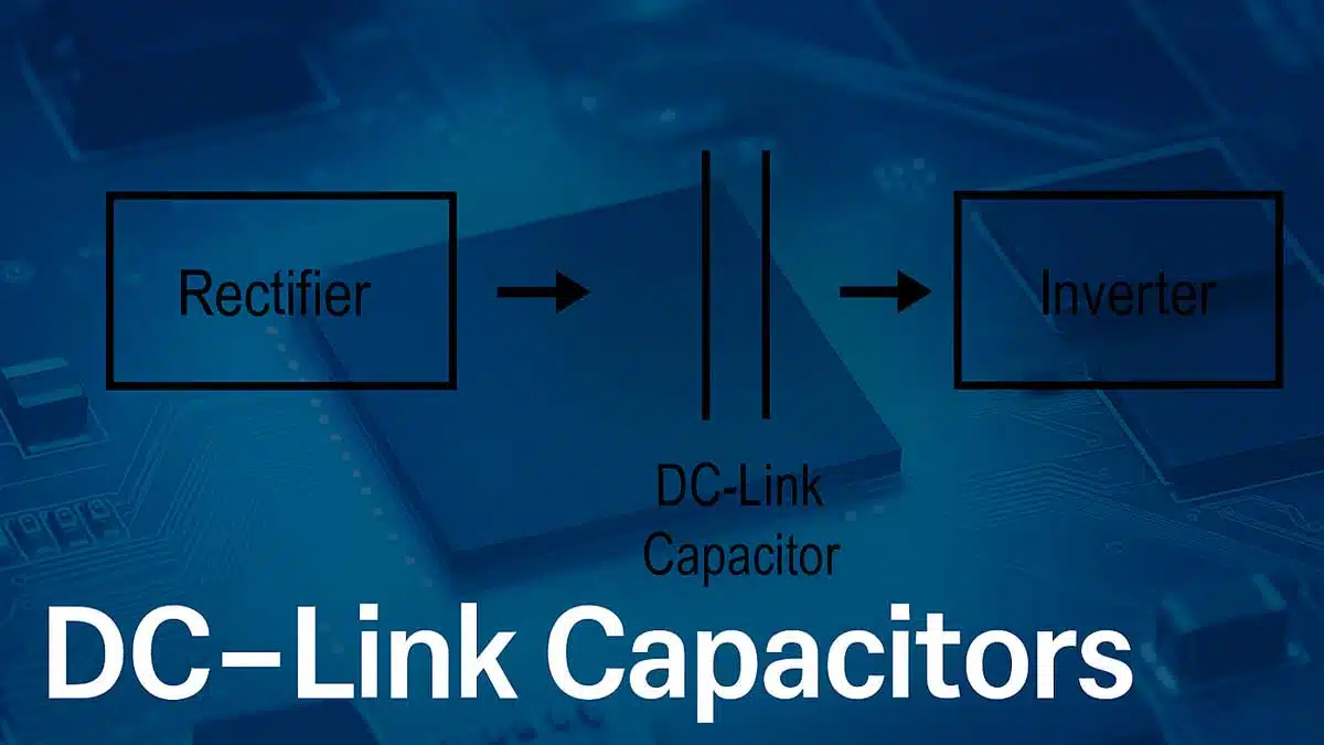
The primary function of a DC-Link capacitor is to smooth the rectified DC voltage and provide a stable supply to the inverter stage. Without this capacitor, voltage ripple from the rectifier would propagate into the inverter, causing inefficiency, electromagnetic interference (EMI), and potential malfunction of sensitive components.
In essence, the capacitor stores energy during voltage peaks and releases it during voltage dips, maintaining a nearly constant DC bus voltage.
The DC-Link capacitor is positioned between the rectifier and inverter, acting as the central energy buffer.
Types of DC-Link Capacitors
Different capacitor technologies are used depending on the application:
| Type | Advantages | Limitations | Typical Applications |
|---|---|---|---|
| Aluminum Electrolytic | High capacitance, cost-effective | Limited lifetime, higher ESR | General-purpose drives, UPS |
| Film Capacitors | Low ESR, high reliability, long lifetime | Larger size, lower capacitance density | EV inverters, renewable energy systems |
| Ceramic Capacitors | Very low ESR, downsizing, temp range | Sensitive to mechanical/thermo mech stress | Wide range of general to High-performance converters |
Applications
DC-Link capacitors are indispensable in a wide range of power electronic systems:
- Renewable Energy: In photovoltaic (PV) inverters and wind turbine converters, they stabilize the DC bus for efficient AC output.
- Electric Vehicles: In traction inverters, they handle high ripple currents and ensure reliable motor control.
- Industrial Drives: Used in variable frequency drives (VFDs) to maintain stable operation of motors.
- Power Supplies: In UPS and SMPS systems, they reduce ripple and improve efficiency.
Design Considerations
When selecting a DC-Link capacitor, engineers must consider:
- Capacitance Value: Determines the ability to store and release energy.
- Voltage Rating: Must exceed the maximum DC bus voltage with safety margin.
- Ripple Current Capability: Defines how much AC current the capacitor can handle without overheating.
- Equivalent Series Resistance (ESR): Lower ESR reduces power losses and heating.
- Lifetime and Reliability: Especially critical in automotive and renewable energy applications.
DC-Link capacitors are the backbone of stable and efficient power conversion systems. Their ability to smooth voltage, absorb ripple, and provide reliable energy buffering makes them indispensable in modern electronics. With the growing demand for renewable energy and electric mobility, the role of DC-Link capacitors will continue to expand, driving innovation in capacitor technology and system design.
DC-Link Capacitors in Automotive Applications
In electric vehicle (EV) applications, DC link capacitors help offset the effects of inductance in inverters, motor controllers, and battery systems.
They also serve as filters that protect EV subsystems from voltage spikes, surges, and electromagnetic interference (EMI).
Take a look at the on-board charger (OBC) in Figure 2, which is responsible for charging the traction battery. Inside the OBC resides:
- The AC/DC converter that converts alternating current (AC) from electric grid into direct current (DC) using rectification and Power Factor Correction (PFC)
- An intermediate DC link circuit for energy buffering
- The next stage DC/DC converter that adjusts the produced DC voltage to provide correct DC levels to the battery.
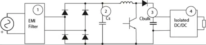
The DC link capacitor Cbulk is placed between the rectifier and DC/DC converter. Desired characteristics for the capacitor include:
- High DC voltage rating: 300V to 500V
- Very large capacitance: 200µF to 1500µF
- Operating temperature range: -40°C to +250°C
- Low equivalent series resistance (ESR): < 1.5mΩ
- High root mean square (RMS) ripple current capacity
- High mechanical ruggedness
To meet the large capacitance values, multiple capacitors or a capacitor array is required. We recommend using our high-capacitance StackiCap 1812-4040 250V-1.2kV 100nF-5.6µF X7R capacitors for such applications. The DC link capacitor must be also able to handle twice the line frequency. Therefore, common circuit arrangements include multilayer ceramic capacitors (MLCCs) connected in parallel with other capacitor technologies to achieve this.
Another EV subsystem where DC link capacitors are found is the inverter in motor drive circuits (shown in Figure 3). The inverter converts DC power from the battery to three-phase AC power to drive the traction motors during acceleration, and then converts AC power back to DC during braking. It also detects the motor’s speed and position and drives the insulated-gate bipolar transistor (IGBT) power stages.
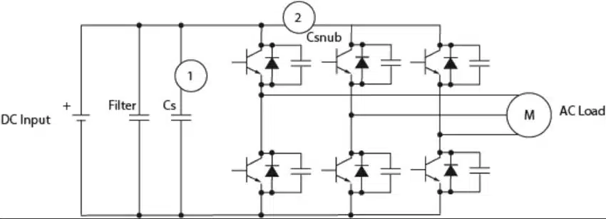
In this subsystem, the DC link or smoothing capacitor Cs is placed in parallel between the DC (battery) and the AC (load) sides of the voltage inverter. The capacitor specifications are very similar to the previous OBC example, and therefore the same StackiCap X7R with high RMS current capacity is recommended. Due to the high capacitance requirements, small-sized MLCCs can be used together with film capacitors and aluminum electrolytic capacitors to integrate closer to the IGBT switching device and improve high frequency attenuation.
Demanding applications possess cost, harsh environmental, and stringent reliability constraints. Although circuit designs can use different approaches, the long-standing core of power conversion designs includes DC-Link capacitors.
DC-Link capacitors can improve system energy density and resolve the physical challenges of ripples introduced by rapid switching that is inherent to switching power conversions. But what type of capacitors work well as DC-Links, and why?
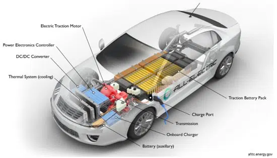
The automotive industry includes a prime example of power conversion in the hybrid and electric powertrain. Battery electric vehicles include a rechargeable bank of batteries to store energy for the drive system, an electric drive motor, and a power controller that includes an inverter. These all operate at high voltages extending from 48 VDC to as high as 800 VDC.
Due to the physical limitations that limit current, high voltage correlates to high performance. The higher the operating DC voltage, the lower the required current flow for the same power output (P=VI).
The automotive industry is well-known for requiring components that can operate with exceeding reliability at extremely high temperatures, under continuous vibration, and where components are subject to harsh environmental conditions. The three-stage traction inverter converts battery power to drive the motor, and the DC-Link capacitor is key to this design.
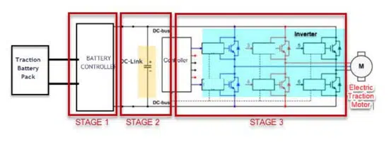
Unlike a toy car, electric vehicles do not operate directly from energy stored in the battery pack; a conversion is needed, Consider a system block diagram including a 3-stage power inverter for a hybrid/electric vehicle (HEV/EV) in Figure 3, where:
- Stage I is the input stage that outputs a DC voltage from the battery pack
- Stage II starts conversion using a DC-Link capacitor which filters and smooths out DC voltage that inhabit the DC bus rails
- Stage III initiates conversion via high-frequency switching (with output much like a rectifier to the rails) and delivers the inverted power to the load as the load creates instantaneous demands
Why the DC-Link Capacitor is Vital
The DC-link capacitor must balance fluctuating instantaneous power on the rails injected by activity from the first and third stages (see Figure 3). The DC-Link capacitor stabilizes the “ripple” generated by Stage III’s high-frequency power switching circuits. Ripple current/voltage (specified at a given frequency and temperature) is the total amount of Root Mean Square (RMS) alternating and direct current/voltage that a capacitor can withstand without failing. The DC-Link capacitor (located in Stage II) must stabilize and smooth out the voltage and current on the rails (i.e., decoupling spikes caused by switching). You can calculate the ripple voltage using this equation:
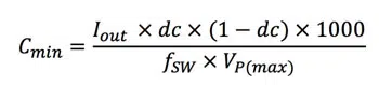
where
- CMIN = required minimum capacitance
- IOUT = output current
- DCycle = duty cycle
- fSW = switching frequency
- Vpp(max) = peak-to-peak ripple voltage
Design Considerations in selecting an Inverter DC-Link capacitor
The DC-link capacitor’s purpose is to provide a more stable DC voltage, limiting fluctuations as the inverter sporadically demands heavy current. A design can use different technologies for DC-Link capacitors such as aluminum electrolytic, film, and ceramic types. The choice is not easy and depends strongly on the application.
Finding the best DC-Link capacitor starts by comparing nominal capacitance values and voltage ratings that translate to known energy requirements, while also shooting for high ripple current ratings. Ripples at DC-Link nodes, primarily generated by furiously fast-switching IGBTs or MOSFETs in Stage III (see Figure 3), affects performance because every real capacitor has some amount of impedance (and self-inductance). The DC-Link capacitor must regulate voltage and absorb ripples in the current, as well.
A ripple wiggles the level of the voltage that appears across the DC-Link capacitor while the switching current’s ripple travels through the capacitor (V=IR). One must also consider inverter switching frequencies that the DC-Link capacitor must tolerate. For instance, film capacitors cannot perform adequately if the switching frequency is greater than 1MHz. Other considerations in choosing a DC-Link capacitor include knowing the DC voltage required at the rails, the expected life of the application, the maximum possible ripple current and frequency that the system will experience, and whether the generated ripple current is steady-state or intermittent.
Datasheets for the better DC-Link capacitors should indicate low self-inductance, very low Equivalent Series Resistance (ESR), and high ripple current tolerance, all at comparable operating temperatures and frequencies amongst the components you are comparing. (A capacitor’s ESR is the total internal resistance as specified at a given frequency and temperature.) The lowest possible ESR will minimize the cast-off heat in the form of dissipated power (PDissipated =I2 x ESR). However, general trade-offs mean that for DC-Link film capacitors, ESR is substantially lower while providing a good capacitance voltage (CV) rating, which typically produces a much better response to ripple current.[1]
Thus, DC-Link film capacitors allow for high ripple current and longer expected life than electrolytic capacitors, while also providing a higher capacitance value than ceramics type capacitors. Nevertheless, the actual requirement of the ripple current rating is difficult to predict and varies depending on the switching frequency and the harmonics that are generated by the input and output stages (i.e., Stage I and III). For example, from the oversimplified block diagram in Figure 3, one could assume a more square-shaped waveform based on the inverter stage. The DC-Link capacitor is the element that sinks or sources the respective currents. Other types of architectures may have a more triangular shape current waveform.
In general, nominal capacitance values can change due to changes in ambient operating temperature or changes in the applied voltage and frequency. Other variables for consideration: self-inductance can significantly reduce a capacitor’s effective impedance at high frequencies, thus changing the capacitor’s expected behavior. Regardless of the type of capacitor chosen, noise suppressors such as KEMET Flex Suppressors® can help suppress high-frequency noise generated by the surrounding environment.
While considering design options, ask whether DC-Link capacitor under consideration can hold up a reasonable level of charge voltage after the input voltage is removed in between switching cycles. To find the amount of energy that is stored in the DC-Link capacitor–to feed the load as the capacitor discharges (as well as the discharge voltage and the hold capacitor values)–calculate hold up capacitance:
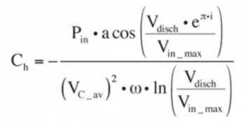
Where
- Vin_max is the peak value of the rectified voltage (Vin_max= • Vline},
- Vdisch is the discharge voltage (Vdisch = /2 • Vin_max) at some load value and line frequency (ω)
- Vline is line voltage
- Pload is load power
- Pin is the inverter’s input average power
- VC_av is the voltage across the average value of Ch:

Furthermore, the ESR of the capacitor is often the limiting factor for the ripple current rating (i.e., the ripple current that the capacitor can handle without overheating). To achieve the needed low ESR and a long lifetime at high dissipation, the physical size of a film capacitor is such that it often results in a capacitor that already meets or surpasses the voltage ripple or hold-up calculations.
Finally, in any high-power design one must consider if cooling is provided and if so, what type? The ambient temperature profile is important to ensure thorough attention to choosing the best DC-Link capacitor.
Capacitors for Demanding Inverter Designs
Several types of capacitors are available. However, not all of them are suitable for high voltage inverters. Suitable multilayer ceramic capacitors with the necessary voltage, temperature readings, and reliability are limited. Electrolytic capacitors are capable choices for a DC-Link application. However, not all electrolytic capacitors can fit the complete bill. Traditional film capacitors have been limited to lower operational temperatures in the past. However, film capacitor technology has been advancing faster than electrolytics. Recent film capacitors such as KEMET’s C4AE can provide a better design response. Metallized film capacitors are smaller than electrolytic capacitors providing similar functionality. Although one could achieve voltage stability by using a large electrolytic capacitor, large components would diminish an automotive inverter’s power density, for instance. Component size and weight contribute to the car’s overall capability and value.
Film capacitors also have a longer life span than electrolytics, mainly because they are constructed from vapor-deposited layers of metal over a substrate material. Due to high levels of energy stored in between the ultrathin layers of metal, an internal short circuit can be naturally self-corrected as small faults get vaporized in microseconds without a noticeable change in performance. Film capacitors are also suitable for high-voltage pulsing applications and corresponding safety concerns, as they can withstand rapid overvoltage and transients. Film capacitors are not polarized, can have a longer operational life (even more so by derating), nearly unlimited shelf life, increased current capacity, provide stable operation across a wider temperature range, and offer better mechanical stability than electrolytic capacitors. Additional benefits include a wide choice in how film capacitors are mounted. And, of particular importance to HEV/EV, robust film capacitors are available at voltage bus levels exceeding 500 VDC.
A good example of film capacitors suitable for HEV/EVs is KEMET’s C4AQ film capacitor, which is AEC-Q200 rated for automotive applications and holds several significant advantages in DC-Link architectures. As mentioned above, KEMET’s C4AQ capacitors have all the superior benefits attributed to film capacitors. Alternatively, KEMET’s C4AE power film capacitors are similar to the C4AQ series of capacitors, but are not automotive-rated. Other capacitors suitable for non-automotive DC-Link applications include CKC Ceramic KC-LINK and C44U and C4DE can film capacitors.
Monitoring can be critical to successful operation for high power inverter design. KEMET’s C/CT series of high current sensors enable real-time current measurement in a live wire. Thermal sensors are often integrated with safety requirements. KEMET’s fast-response OHD thermal sensors are dust, explosion, and corrosion proof with a wide range of operating temperatures up to 120°C.
As demonstrated above, selecting the appropriate DC-Link Capacitor can be an involved, but critically important, process. KEMET has the products and people necessary to streamline this process for you.
[1] https://passive-components.eu/film-capacitors-characteristics-and-uses-in-power-applications/
DC-Link Capacitors: Frequently Asked Questions
A DC-Link capacitor smooths rectified DC voltage, stabilizes the DC bus, and reduces ripple. It acts as an energy buffer between rectifier and inverter stages, ensuring efficient and reliable power conversion.
They are widely used in renewable energy inverters, electric vehicles, industrial motor drives, UPS systems, and medical equipment power supplies.
Common types include aluminum electrolytic (high capacitance, lower lifetime), film capacitors (low ESR, long life), and ceramic capacitors (very low ESR, compact size). Hybrid solutions often combine these technologies.
Key parameters include capacitance value, voltage rating, ripple current capability, equivalent series resistance (ESR), lifetime, and reliability under harsh conditions.
In EVs, DC-Link capacitors stabilize inverter circuits, filter voltage spikes, and handle high ripple currents, ensuring safe and efficient motor control and battery charging.
How to Select the Right DC-Link Capacitor
How to Select the Right DC-Link Capacitor
- Define Application Requirements
Identify whether the capacitor will be used in renewable energy, automotive, industrial drives, or power supply systems.
- Determine Voltage and Capacitance
Select a voltage rating above the maximum DC bus voltage with safety margin, and calculate the required capacitance for energy buffering.
- Evaluate Ripple Current and ESR
Ensure the capacitor can handle expected ripple currents without overheating. Choose low ESR to minimize power losses and heating.
- Consider Lifetime and Reliability
For demanding environments like EVs or renewable energy, prioritize capacitors with long operational life and high mechanical robustness. Consider temperature and environmental impact.
- Select the Technology
Choose between electrolytic (cost-effective, high capacitance), film (low ESR, long life), or ceramic (compact, high-frequency performance), or combine them for hybrid performance.