


Paul Martin from Omnexus, a SpecialChem company put together a comprehensive article on Dissipation Factor of Plastic Materials which includes Min Value (°C) & Max Value (°C) table. This may be quite useful when evaluation various plastic polymer material properties.
Plastics and Importance of DF
Dissipation factor (DF or tan δ) is the electrical property of plastics and other electrical insulating materials. It is defined as the reciprocal of the ratio between the insulating materials’ capacitive reactance to its resistance (Equivalent Series Resistance or ESR) at a specified frequency.
In other words, it is defined as a ratio between the permittivity and the conductivity of an electrical insulating material
The property is also referred as the tangent of the loss angle, loss tangent, tan delta, approx. power factor…
It measures the electrical energy absorbed and lost (power dissipation) when electrical current is applied to an insulating material. Most of the absorbed energy is dissipated as heat.
Dissipation factor indicates the inefficiency of material to hold energy or behave as an insulating material. The lower the dissipation factor, the more efficient is the insulator system. Most plastics have relatively lower dissipation factor at room temperature.
Dissipation Factor is a dimensionless measure and hence no units.
Applications include:
The low dissipation factors indicated high-quality, high performance electrical or electronic systems. It is important for plastic insulators in high-frequency applications such as radar equipment or microwave parts.
Low values mean better dielectric materials with less dielectric heating
The high dissipation factors are important for polymers that are to be heated in a radio frequency or microwave oven for welding or drying etc. Also, material used for high capacitance requires high dielectric constant and low dissipation factor.
Dissipation factor can also be used to assess the characteristics or quality of an insulating material in applications such as cable, terminations, joints etc. for moisture content, deterioration etc. However, here initial values of dissipation factor of tested material are important.
How to Calculate Dissipation Factor of an Insulator?
Dissipation factor is the tangent of the loss angle of the insulating material.
In an ideal capacitor without any dielectric losses, the insulation current is exactly 90° leading according to the applied voltage. As dielectric becomes less than 100% efficient, when the current wave begins to lag the voltage in direct proportion.
The dielectric phase angle, θ, is the angular difference in phase between the sinusoidal alternating potential difference applied to a dielectric and the component of the resulting current having the same period as the potential difference.
Essentially, this means that when an alternating current is applied across an insulating material, the resulting alternating current passing through it (no matter how small) will be at a different phase than the voltage.
The amount of current wave deviates from being 90° out of phase with voltage is defined as the dielectric loss angle (90°- θ). The tangent of this angle δ is known as the loss tangent or dissipation factor.
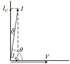
| Phasor Diagram for tan δ Measurement The tan δ measured at a frequency ω and voltage V, is the ratio of the resistive (IR) and the capacitive (IC) currents according to: |
 |
Dissipation Factor Vs. Power Factor
The power factor of an insulator is defined as the ratio of power dissipated in watts to total charging volt-amperes or it is the cosine of the angle between the voltage applied and the current resulting i.e. the dielectric phase angle θ.

If the dissipation factor (tan δ) is very small – typically less than 10%, then the dissipation factor and the power factor differ in a negligible amount and can be assumed to have the same value.
Dielectric loss factor or loss factor of a material is an another frequently used term. It is the product of dielectric constant and the dissipation factor. It is related to the total loss of power occurring in plastics or any other insulating materials. Or how easily the material will heat up in a high frequency field.
Dissipation Factor of Plastics
Plastic materials are mostly exhibiting good insulation properties and thus some of them are used as a common dielectric materials for plastic organic film capacitors.
Standard Methods Used to Determine DF
The most generally used standard tests to calculate dissipation factor for plastics are ASTM D2520, ASTM D150 or IEC 60250 (of course there exist several other methods as well, but they are not discussed here).
The method includes:
A sample is placed between two metallic plates and capacitance is measured. A second run is measured without the specimen between the two electrodes. The ratio of the power dissipated in the test material to the power applied is dissipation factor:
- The test can be conducted at different frequencies, often between the 10Hz and 2MHz range
- The sample must be flat and larger than the 50mm (2 in) circular electrodes used for the measurement
Factors Influencing Dissipation Factor
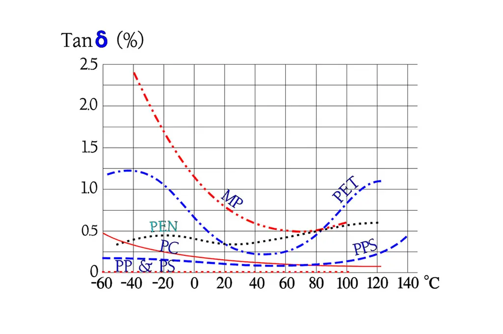
Factors such as frequency, temperature, voltage, humidity, and weathering affect dissipation factor of plastics to varying degrees, depending on the level and duration of exposures.
- Frequency: The changes in dielectric constant and loss index with frequency are produced by the dielectric polarizations that exists in the material
- Temperature: Dissipation factor increases with increase in temperature or humidity. With this increase often being dramatic or even destructive at the glass transition temperature of plastics
- Humidity: Increase in humidity increased the magnitude of the material’s interfacial polarization, this increases conductance. These humidity effects are caused by the absorption of water or formation of an ionized water film on the surface
- Weathering: Rains, severe winds, impurities in atmosphere, UV light, heat etc. may change the surface of an insulating material either physically (roughening, cracking…) or chemically leading to water penetration into the material volume
Find commercial grades matching your electrical properties target using “Property Search – Dissipation Factor filter in Omnexus Plastics Database:

Dissipation Factor (DF) Values of Several Plastics
| Polymer Name | Min Value | Max Value |
| ABS – Acrylonitrile Butadiene Styrene | 50 | 190 |
| ABS Flame Retardant | 70 | 90 |
| ABS High Heat | 20 | 350 |
| ABS High Impact | 20 | 350 |
| ABS/PC Blend – Acrylonitrile Butadiene Styrene/Polycarbonate Blend | 70 | 200 |
| ABS/PC Blend 20% Glass Fiber | 20 | 90 |
| ABS/PC Flame Retardant | 40 | 70 |
| Amorphous TPI Blend, Ultra-high heat, Chemical Resistant (Standard Flow) | 0.001 | 0.001 |
| ASA – Acrylonitrile Styrene Acrylate | 90 | 340 |
| ASA/PC Blend – Acrylonitrile Styrene Acrylate/Polycarbonate Blend | 20 | 190 |
| ASA/PC Flame Retardant | 110 | 170 |
| CA – Cellulose Acetate | 100 | 1000 |
| CAB – Cellulose Acetate Butyrate | 100 | 400 |
| CP – Cellulose Proprionate | 60 | 300 |
| CPVC – Chlorinated Polyvinyl Chloride | 100 | 200 |
| ECTFE – Ethylene Chlorotrifluoroethylene | 130 | 170 |
| ETFE – Ethylene Tetrafluoroethylene | 6 | 100 |
| EVA – Ethylene Vinyl Acetate | 130 | 1000 |
| EVOH – Ethylene Vinyl Alcohol | 1800 | 2200 |
| FEP – Fluorinated Ethylene Propylene | 7 | 7 |
| HDPE – High Density Polyethylene | 3 | 20 |
| HIPS – High Impact Polystyrene | 4 | 20 |
| HIPS Flame Retardant V0 | 5 | 50 |
| Ionomer (Ethylene-Methyl Acrylate Copolymer) | 20 | 20 |
| LCP – Liquid Crystal Polymer | 40 | 40 |
| LCP Glass Fiber-reinforced | 60 | 300 |
| LCP Mineral-filled | 70 | 280 |
| LDPE – Low Density Polyethylene | 3 | 4 |
| MABS – Transparent Acrylonitrile Butadiene Styrene | 2.8 | 3 |
| PA 11 – (Polyamide 11) 30% Glass fiber reinforced | 0.03 | 0.03 |
| PA 11, Conductive | 0.05 | 0.25 |
| PA 11, Flexible | 0.05 | 0.25 |
| PA 11, Rigid | 0.05 | 0.25 |
| PA 12 (Polyamide 12), Conductive | 0.05 | 0.25 |
| PA 12, Fiber-reinforced | 0.05 | 0.25 |
| PA 12, Flexible | 0.05 | 0.25 |
| PA 12, Glass Filled | 0.05 | 0.25 |
| PA 12, Rigid | 0.05 | 0.25 |
| PA 46 – Polyamide 46 | 190 | 600 |
| PA 46, 30% Glass Fiber | 23 | 90 |
| PA 6 – Polyamide 6 | 100 | 600 |
| PA 6-10 – Polyamide 6-10 | 400 | 400 |
| PA 66 – Polyamide 6-6 | 100 | 400 |
| PA 66, 30% Glass Fiber | 100 | 1500 |
| PA 66, 30% Mineral filled | 200 | 1500 |
| PA 66, Impact Modified, 15-30% Glass Fiber | 130 | 200 |
| PA 66, Impact Modified | 100 | 2000 |
| Polyamide semi-aromatic | 3 | 3.1 |
| PAI – Polyamide-Imide | 60 | 710 |
| PAI, 30% Glass Fiber | 220 | 500 |
| PAR – Polyarylate | 20 | 200 |
| PBT – Polybutylene Terephthalate | 10 | 200 |
| PBT, 30% Glass Fiber | 20 | 120 |
| PC (Polycarbonate) 20-40% Glass Fiber | 9 | 75 |
| PC (Polycarbonate) 20-40% Glass Fiber Flame Retardant | 9 | 100 |
| PC – Polycarbonate, high heat | 69 | 100 |
| PC/PBT blend, Glass Filled | 100 | 200 |
| PCTFE – Polymonochlorotrifluoroethylene | 10 | 250 |
| PE – Polyethylene 30% Glass Fiber | 20 | 80 |
| PEEK – Polyetheretherketone | 30 | 30 |
| PEEK 30% Carbon Fiber-reinforced | 29 | 32 |
| PEEK 30% Glass Fiber-reinforced | 20 | 20 |
| PEI – Polyetherimide | 13 | 25 |
| PEI, 30% Glass Fiber-reinforced | 15 | 53 |
| PEI, Mineral Filled | 10 | 15 |
| PEKK (Polyetherketoneketone), Low Cristallinity Grade | 0.004 | 0.004 |
| PESU – Polyethersulfone | 10 | 140 |
| PESU 10-30% glass fiber | 70 | 100 |
| PET – Polyethylene Terephtalate | 20 | 200 |
| PET, 30% Glass Fiber-reinforced | 120 | 1680 |
| PET, 30/35% Glass Fiber-reinforced, Impact Modified | 1.5 | 1.5 |
| PETG – Polyethylene Terephtalate Glycol | 20 | 300 |
| PE-UHMW – Polyethylene -Ultra High Molecular Weight | 2 | 2 |
| PFA – Perfluoroalkoxy | 2 | 2 |
| PI – Polyimide | 18 | 50 |
| PMMA – Polymethylmethacrylate/Acrylic | 200 | 200 |
| PMMA (Acrylic) High Heat | 400 | 600 |
| PMMA (Acrylic) Impact Modified | 300 | 400 |
| PMP – Polymethylpentene | 0.7 | 30 |
| POM – Polyoxymethylene (Acetal) | 50 | 110 |
| POM (Acetal) Impact Modified | 50 | 250 |
| POM (Acetal) Low Friction | 20 | 90 |
| POM (Acetal) Mineral Filled | 1.5 | 1.6 |
| PP – Polypropylene 10-20% Glass Fiber | 10 | 20 |
| PP, 10-40% Mineral Filled | 7 | 11 |
| PP, 10-40% Talc Filled | 7 | 11 |
| PP, 30-40% Glass Fiber-reinforced | 10 | 20 |
| PP (Polypropylene) Copolymer | 3 | 5 |
| PP (Polypropylene) Homopolymer | 3 | 5 |
| PP, Impact Modified | 3 | 5 |
| PPA – Polyphthalamide | 270 | 270 |
| PPA, 33% Glass Fiber-reinforced – High Flow | 0.014 | 0.016 |
| PPA, 45% Glass Fiber-reinforced | 0.9 | 0.2 |
| PPE – Polyphenylene Ether | 4 | 9 |
| PPE, 30% Glass Fiber-reinforced | 10 | 15 |
| PPE, Flame Retardant | 7 | 31 |
| PPS – Polyphenylene Sulfide | 4 | 30 |
| PPS, 20-30% Glass Fiber-reinforced | 10 | 32 |
| PPS, 40% Glass Fiber-reinforced | 13 | 20 |
| PPS, Glass fiber & Mineral-filled | 70 | 580 |
| PPSU – Polyphenylene Sulfone | 17 | 50 |
| PS (Polystyrene) 30% glass fiber | 5 | 28 |
| PS (Polystyrene) Crystal | 1 | 28 |
| PS, High Heat | 1 | 28 |
| PSU – Polysulfone | 8 | 64 |
| PSU, 30% Glass finer-reinforced | 40 | 60 |
| PTFE – Polytetrafluoroethylene | 2 | 2 |
| PTFE, 25% Glass Fiber-reinforced | 5 | 5 |
| PVC, Plasticized | 400 | 1600 |
| PVC, Plasticized Filled | 400 | 1600 |
| PVC Rigid | 60 | 200 |
| PVDF – Polyvinylidene Fluoride | 200 | 1700 |
| SAN – Styrene Acrylonitrile | 70 | 100 |
| SAN, 20% Glass Fiber-reinforced | 10 | 100 |
| SMA – Styrene Maleic Anhydride | 40 | 40 |
| SMMA – Styrene Methyl Methacrylate | 400 | 400 |