Passive Components Blog
No Result
View All Result
  • Home
  • NewsFilter
    • All
    • Aerospace & Defence
    • Antenna
    • Applications
    • Automotive
    • Capacitors
    • Circuit Protection Devices
    • electro-mechanical news
    • Filters
    • Fuses
    • Inductors
    • Industrial
    • Integrated Passives
    • inter-connect news
    • Market & Supply Chain
    • Market Insights
    • Medical
    • Modelling and Simulation
    • New Materials & Supply
    • New Technologies
    • Non-linear Passives
    • Oscillators
    • Passive Sensors News
    • Resistors
    • RF & Microwave
    • Telecommunication
    • Weekly Digest

    KYOCERA AVX Releases Compact High-Directivity Couplers

    Supercapacitors Emerge as a Promising Solution to AI-Induced Power Energy Spikes

    Wk 18 Electronics Supply Chain Digest

    YAGEO Releases High Current SMD Common Mode Choke With Shape Core Construction

    Murata and NIMS Built New Database of Dielectric Material Properties

    Tariffs Crush Sales Sentiment in April 2025 ECST Results

    High-Density PCB Assemblies For Space Applications

    Solid State Polymer Multilayer Capacitors For High Temperature Application

    Graphene-Based BOSC Bank Of Supercapacitor Cells

    Trending Tags

    • Ripple Current
    • RF
    • Leakage Current
    • Tantalum vs Ceramic
    • Snubber
    • Low ESR
    • Feedthrough
    • Derating
    • Dielectric Constant
    • New Products
    • Market Reports
  • VideoFilter
    • All
    • Antenna videos
    • Capacitor videos
    • Circuit Protection Video
    • Filter videos
    • Fuse videos
    • Inductor videos
    • Inter-Connect Video
    • Non-linear passives videos
    • Oscillator videos
    • Passive sensors videos
    • Resistor videos

    Coupled Inductors in Multiphase Boost Converters

    VPG Demonstrates Precision Resistor in Cryogenic Conditions

    Comparison Testing of Chip Resistor Technologies Under High Vibration

    EMC Challenges for High Speed Signal Immunity and Low EMI

    MOSFET Gate Drive Resistors Power Losses

    Modified Magnetic Reluctance Equivalent Circuit and its Implications

    Improving Common Mode Noise Reduction while Decreasing BOM

    Die and Wire PCB Bonding Explained

    Rogowski Coil Current Sensor Explained

    Trending Tags

    • Capacitors explained
    • Inductors explained
    • Resistors explained
    • Filters explained
    • Application Video Guidelines
    • EMC
    • New Products
    • Ripple Current
    • Simulation
    • Tantalum vs Ceramic
  • Knowledge Blog
  • Suppliers
    • Who is Who
  • Events
No Result
View All Result
Passive Components Blog
No Result
View All Result

Dual-Mode Chokes Expand Inverters Capabilities

2.4.2019
Reading Time: 5 mins read
A A

Source: Power Electronics article

by: Michael Freitag,  director of magnetics product management at KEMET Corp.

RelatedPosts

KYOCERA AVX Releases Compact High-Directivity Couplers

Supercapacitors Emerge as a Promising Solution to AI-Induced Power Energy Spikes

Wk 18 Electronics Supply Chain Digest

Innovative hybrid filters built with the latest magnetic materials enable lightweight, miniaturized inverters to satisfy the latest green-energy and mobility applications.

Important changes in the way electricity is generated and used—such as increasing reliance on energy from renewable sources, the change to efficient variable-speed drives in industrial and domestic appliances, and adoption of hybrid or battery-electric vehicles—are increasing demands for electronic inverters that can be controlled to provide ac power at a desired voltage and frequency.

Taking renewable energy as an example, utility companies’ strategies are moving toward distributed power generation, with micro generators feeding into the grid at multiple points in the network. There’s also interest in small non-grid-tied generators for deployment on consumer or farming and light commercial/industrial sites.

Such applications demand compact and low-cost electronic power conditioning. This would enable conversion of the harmonic-rich and unstable output of a wind turbine, or the changing dc output of an array of photovoltaic panels, first into high-voltage, capacitor-stabilized dc that’s then input to an inverter to generate a consistent ac waveform at a frequency suitable for feeding into the grid.

Similarly, in hybrid/EV or motor drives, where constantly adjusting the inverter’s output frequency using logic or software commands is key to controlling the motor speed, compact dimensions, low weight, and affordability are critical to ensure market growth.

Operating Principles and Noise Sources

An inverter like the bridge inverter shown in Figure 1 commutates current through the load by turning on and off the upper and lower power switches in alternate legs in sequence. The power switches may be insulated gate bipolar transistors (IGBTs) or super-junction MOSFETs, or—in high-end applications such as premium electric vehicles or where ultimate energy efficiency is required—wide-bandgap devices such as silicon-carbide (SiC) MOSFETs. Each gate is controlled in sequence relative to all others using a pulse-width-modulated (PWM) signal.


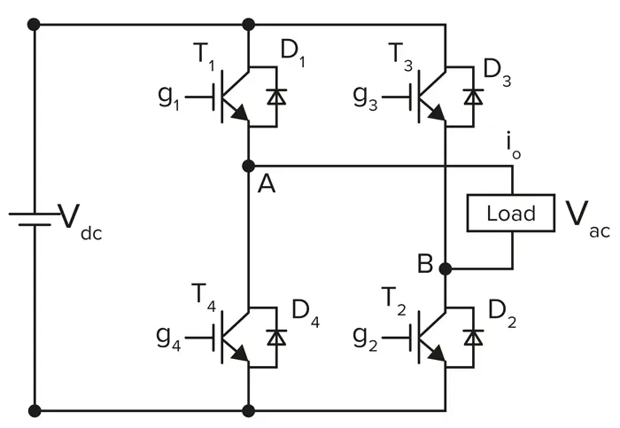
1. Shown is a simple single-phase full-bridge inverter.

If the power switches are IGBTs, the frequency of the PWM signals applied to each gate is typically about 20 kHz. MOSFETs can operate at much higher frequencies up to several hundred kilohertz. In either case, rapid switching produces abrupt changes in voltage across the transistors, causing oscillations containing high-frequency noise at harmonics of the switching frequency.

In any IGBT-based inverter for a wind or solar generator, noise signals can exist at frequencies up to 1 MHz or more. These and other sources of noise such as dc-dc converter switching elsewhere in the system, coupled onto the ac output power lines, can impair the output power quality and cause interference. This can affect the system’s own control signals, such as analog feedback signals, as well as nearby equipment.

To prevent such distortion and interference, standards such as IEEE 1547 and UL 1741, which apply to inverters for distributed-power systems like wind or solar generators, impose limits on the harmonic content allowed in the inverter output. Radiated electromagnetic interference (EMI) is also subject to limits imposed by standards such as FCC Part 15 B.

Mitigating Switching Noise

To comply with applicable specifications on noise and electromagnetic compatibility, filters placed throughout the system remove harmonics from voltage and current waveforms, correct the power factor by ensuring voltage and current waveforms are in phase, and minimize distortion.

Figure 2 shows the locations of filters for attenuating noise in a solar-energy power-conditioning system. The filter at the output of the inverter is designed to remove switching frequency transients. It contains a combination of X and Y capacitors, inductors, and chokes to remove common-mode and differential-mode noise at the main harmonics of the switching frequency.

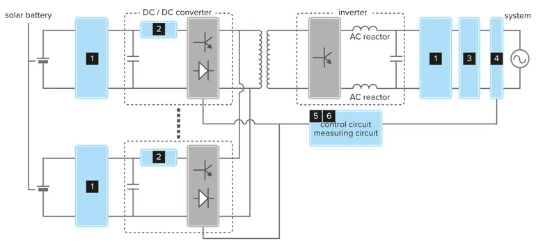
2. Here are the main functional blocks of a solar power-conditioning system, highlighting filtering requirements. source: Komet

Figure 3 provides more detail on the composition of the filter. In principle, X capacitors and chokes remove differential-mode noise, while Y capacitors and common-mode inductors remove common-mode noise. Common-mode noise appears in the same direction on two conductors, whereas differential-mode noise appears in opposite directions on two conductors.

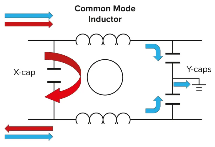
3. Chokes and capacitors at the inverter output attenuate common-mode (blue) and differential (red) noise. Source: Komet

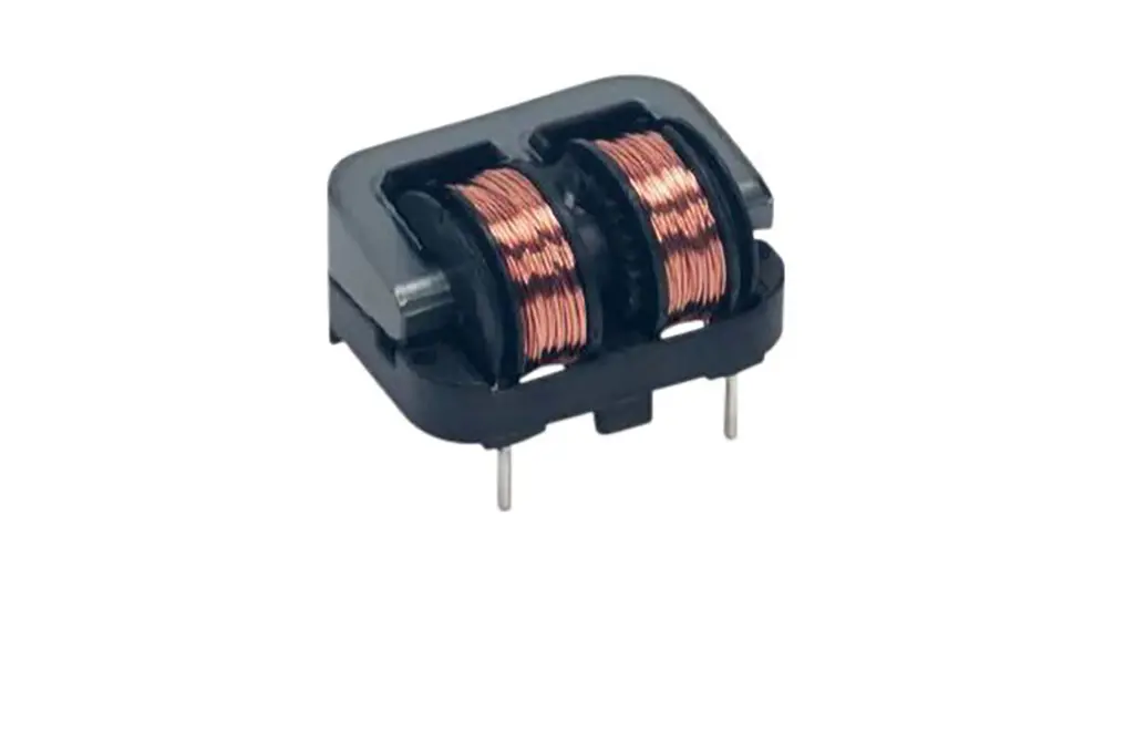
The common-mode choke coil as shown in Figure 3 is a four-terminal device that comprises two conducting wires wrapped in opposite directions around a single magnetic core. Conventionally, this core consists of ferrite material. Since magnetic flux flows inside the core, common-mode choke coils act as inductors that provide high impedance against common-mode (noise) currents while allowing wanted differential currents to pass.

As far as the common -mode choke is concerned, identical currents flowing in opposite directions through the choke windings will create equal and opposite magnetic fields that cancel each other out. Therefore, the choke presents minimal impedance to the current flowing into the load and back through the return path. Differential noise refers to distortions that cause differences between these two currents. The magnetic fields due to these different signals will not cancel out; instead, they will present high impedance that attenuates the distortion.

Advanced Filter Technologies for Lightweight Inverters

Growing reliance on renewable energy, electric vehicles, and diverse motor drives continues to push demand for inverters that are compact, lightweight, and affordable. Consequently, the industry is looking for ways to reduce the size, weight, and cost of typically bulky components like filtering capacitors and chokes.

Addressing this issues, proprietary ferrite core materials developed by KEMET help greatly reduce the size of standard chokes. In addition, they make it possible to create dual-mode chokes that combine common-mode and differential-mode filtering in the same package. The overall dimensions are similar to those of a comparable conventional common-mode choke. Figure 4illustrates the principle.

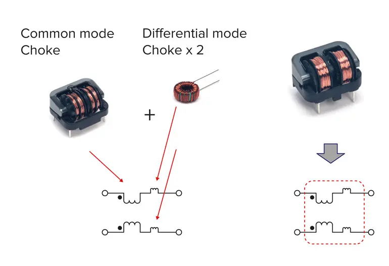
4. Dual-mode chokes integrate three magnetic components, saving solution size and part count. Source: Komet

KEMET also leveraged the extra design flexibility afforded by its proprietary materials to optimize the shape of these dual-mode chokes. The end result is significantly enhanced differential-mode (normal mode) noise suppression.

Figure 5 illustrates the high performance of the SSHB10 dual-mode chokes, presenting high impedance to both common-mode and differential-mode noise. The standard type, represented in this diagram by the SSHB10H-04320, is optimized for high-temperature performance. The SSHB10H-R04760 features a core material of increased permeability, which further boosts impedance to common-mode noise while maintaining identical differential-mode performance. Both chokes are rated for current up to 3 A.

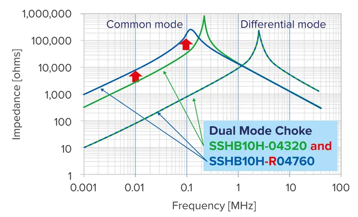
5. Comparison of new dual-mode choke versus conventional common-mode choke. Source: Kemet

Conclusion

Demand for compact, lightweight power inverters is expected to rise, across green-energy, industrial, and automotive markets. Advanced magnetic technologies that can significantly slim bulky noise filters and reduce component count now give designers extra freedom to achieve these goals.

Download this article in pdf here

featured image credit: Kemet


Related

Recent Posts

KYOCERA AVX Releases Compact High-Directivity Couplers

7.5.2025
14

Supercapacitors Emerge as a Promising Solution to AI-Induced Power Energy Spikes

6.5.2025
33

YAGEO Releases High Current SMD Common Mode Choke With Shape Core Construction

5.5.2025
21

Murata and NIMS Built New Database of Dielectric Material Properties

5.5.2025
42

Tariffs Crush Sales Sentiment in April 2025 ECST Results

5.5.2025
57

Solid State Polymer Multilayer Capacitors For High Temperature Application

2.5.2025
28

Würth Elektronik Offers New Power Supplies Development Kit

29.4.2025
37

Bourns Extends Shielded Power Inductors by Four New Series

29.4.2025
18

Shielding Cabinets

29.4.2025
17

Magnetic Shielding and Magnetic Shielding Sheets

29.4.2025
25

Upcoming Events

May 14
11:00 - 12:00 CEST

Reliable RIGID.flex PCBs for Critical Applications – Made in Europe

May 28
16:00 - 17:00 CEST

Power Over Data Line

View Calendar

Popular Posts

  • Buck Converter Design and Calculation

    0 shares
    Share 0 Tweet 0
  • Boost Converter Design and Calculation

    0 shares
    Share 0 Tweet 0
  • Flyback Converter Design and Calculation

    0 shares
    Share 0 Tweet 0
  • Tariffs Crush Sales Sentiment in April 2025 ECST Results

    0 shares
    Share 0 Tweet 0
  • What is a Dielectric Constant and DF of Plastic Materials?

    4 shares
    Share 4 Tweet 0
  • LLC Resonant Converter Design and Calculation

    0 shares
    Share 0 Tweet 0
  • Ripple Current and its Effects on the Performance of Capacitors

    3 shares
    Share 3 Tweet 0
  • Dual Active Bridge (DAB) Topology Explained

    0 shares
    Share 0 Tweet 0
  • SEPIC Converter Design and Calculation

    0 shares
    Share 0 Tweet 0
  • Flying Capacitors Explained

    0 shares
    Share 0 Tweet 0

Newsletter Subscription


Passive Components Blog

© EPCI - Leading Passive Components Educational and Information Site

  • Home
  • Privacy Policy
  • EPCI Membership & Advertisement
  • About

No Result
View All Result
  • Home
  • Knowledge Blog
  • Premium Suppliers

© EPCI - Leading Passive Components Educational and Information Site

This website uses cookies. By continuing to use this website you are giving consent to cookies being used. Visit our Privacy and Cookie Policy.
Go to mobile version