


Source: EPCI ABC of CLR article
Ferrite equivalent circuits
Most engineers think of ferrite as an inductive component with which coils, transformers, choke etc. can be manufactured. Losses in the material are accepted as an annoyance and best avoided and are seen to mark a limit of the operating frequency range.The theoreticians had the misfortune of choosing an unsuitable model to describe the frequency dependent parameters, which impedes further understanding like a wall. The new parallel equivalent circuit is logical, simple and comfortable for measurement and handling. It becomes very obvious if one measures values well above of the permissible working range for the coil application. Here the (desired) losses represent the main impedance component of a ferrite component.
Because, when fighting electromagnetic noise, it makes little sense to want to suppress it using reactances. Reactances reflect interfering energy; ferrites with losses absorb the energy (conversion to heat).
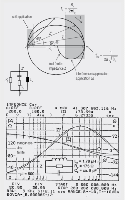
Fig. 1.51: Equivalent circuits for ferrite tube or ferrite toroidal cores
This should just explain the most important equivalent circuit structures, measured with the HP4195A. Figure 1.51 shows the parallel equivalent circuit model, derived from measured ferrite impedances Z(f) in terms of magnitude and phase under low driving conditions. Impedances Z were measured with a special holding device, permitting as short a conductor loop through the ferrite tube as possible. The parameters of the parallel equivalent circuit are Lp, Rp, Cp and possibly r (for manganese-zinc-ferrites).
Figure 1.51 shows the phase diagram of a parallel oscillating circuit as circuit Z’ and a real phasor diagram Z of a manganese-zinc ferrite. If several winding turns are wound through the tube core, there is an increase of Z(n) = Z · n2 minus the effects of the coil capacitance. Transformer and filter constructors should also calculate the equivalent circuit of their core.
Manganese-zinc ferrites are used as the noise suppression material for the short-wave range µi = 2000 → µi = 600. The frequency

at which Q (Z) = 45° is correlated with the initial permeability µi of the material. µi · fg ≈ 5000 MHz – 10000 MHz. The losses are only determined by the relationship

The high DC current through the tube core, i.e. from inductance below 200 mT–400 mT, causes saturation in the ferrite material and the effect as inductance and loss resistance disappears.
The complex impedance is transformed into the inserted conductor as though it had been cut through and the equivalent circuit soldered in between. The same principle also applies for several winding turns and complete coils (The core of broadband transformers also has a constant parallel resistance). Manganese-zinc ferrites are the material used for classical coil filter. Their disadvantage is their huge internal dielectric constant er > 102, which is a reason for the high capacitance in the equivalent circuit. The parallel resistance Rp falls to between 1/2 and 1/3 of the maximum value at high frequencies. The higher the initial permeability µi, the lower is the 45° limit frequency fg = Rp/(2 · p · Lp). The application range of this material as an interference power absorber starts above approx. 2 · fg.
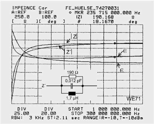
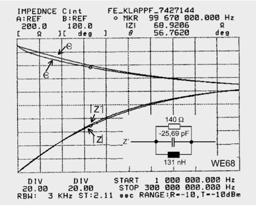
Fig.: 1.52: Equivalent circuits on nickel-zinc ferrites
Figure 1.52 shows equivalent circuits for Ni-Zn ferrites, which have a lower Cp but are only useful above 20 MHz due to their low permeability. Classical EMC interference sources have a spectrum concentrated well below 20 MHz. The nickel-zinc ferrites, which are otherwise useful up to high frequencies as a result of their low parallel capacitance, have a problem: To become effective down to low frequencies(< 10 MHz), materials with high µi have to be synthesized.
Above µi = 800–1000 the Curie temperature falls below +125° (above the Curie temperature, the ferrite ring is unmagnetic and unresponsive). Figure 1.52 shows two Z measurement curves on a logarithmic scale. One can see agreement with the model and the high consistency at 200 MHz. As a result of the high specific resistance, one could manufacture sophisticated SMD “ferrite beads” using sintered conductor tracks, which would permit EMC measures in densely packed electronic componentry.
A suitably selected series circuit made of manganese and nickel-zinc ferrites is the ideal EMC absorption medium with a simple reproduction of L parallel to R.
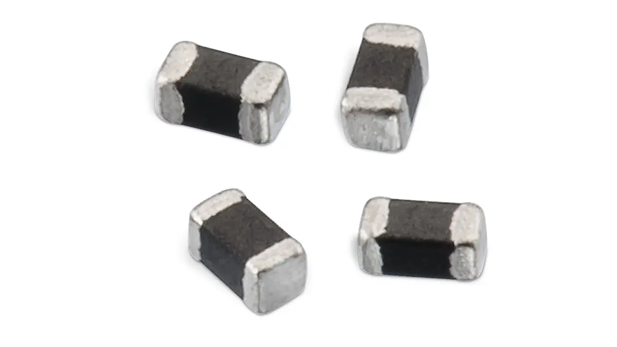
Typical measuring results for SMD ferrites:

Fig. 1.53: Impedance-phase curve for ferrite choke 742 792 13 (600 Ω at 100 MHz)
Figure 1.53 shows the impedance-phase graph against frequency for the SMD ferrite 742 792 13. The flat section of the phase curve and the associated low quality factor in the region of impedance maximum do not allow any resonance. This is an indication that the resistive (“ohmic”) component of impedance is very large. A standard RCL measuring bridge with 1 kHz test voltage measures the following data.

Simulation of the component on an impedance analyzer at 100 MHz results in the equivalent circuit in Figure 1.54.

Fig. 1.54: Equivalent circuit of the ferrite 742 792 13 at f = 100 MHz
The high resistive component of the impedance may be clearly identified.
The following parameters are measured using an impedance measuring bridge at 100 MHz.
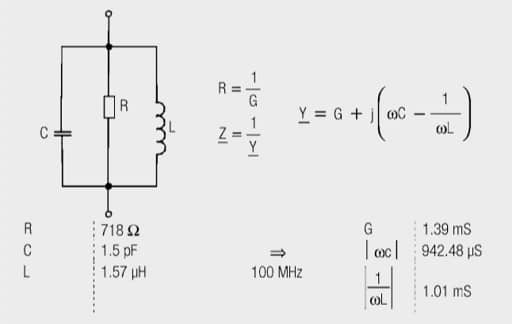
Fig. 1.55: Parameters for impedance measurement of the ferrite
The impedance can be checked with the aid of the equivalent circuit in Figure 1.55 with the use of parameters measured with the measurement bridge.

The simulated or calculated values correspond well with the measurement values of the graph and illustrate the component’s functionality. At 1.5 pF, the parasitic capacity is low, so that the ferrite can also be used up to the highest frequency range (≈ 1000 MHz). At a current rating of 200 mA the impedance at 100 MHz drops to 480 Ω (within the permissible tolerance of ±25%), the impedance maximum is shifted to higher frequencies (Figure 1.56).

Fig. 1.56: Impedance and phase curve for the SMD ferrite 742 792 13 loaded with a 200 mA current
The reason for the shift is the saturation of the ferrite material. The DC current component generates a so-called unipolar field within the choke, which superimposes with the AC field component. The ferrite’s unipolar losses shift the working point of the ferrite material on the magnetization curve. The respective ferrite choke impedance curve is dependent on the amplitude and frequency of the AC field component and on the DC current component.

Fig. 1.57: Family of impedance curves dependent on the DC current of SMD ferrite 742 792 04
The situation often occurs that a DC current flows through an SMD ferrite in addition to the signal current. This DC current induces a high field strength in the ferrite. Core saturation takes place above a certain current level, which leads to a drop in permeability and therefore impedance. It may be seen from Figure 1.57 that this effect is particularly pronounced around approx. 150 MHz and becomes lower with increasing frequency. Above 300–350 MHz a rise in impedance may be observed, caused by an increase in the real permeability.
This effect is not considered in the following equivalent circuit parameters. At low signal levels and low DC current the results obtained are sufficient.
However, at high DC currents this effect should not be ignored. Current-dependent equivalent circuits can be developed and used for this purpose. Their complexity cannot of course be compared with conventional parallel equivalent circuits.
For this reason, they are already integrated in the LTspice simulation software. It is only necessary to access the component library “FerriteBead_Z(I)” for selecting components. The required SMD ferrite can be subsequently selected with a right click on the electronic symbol. The following graph is for a test simulation in order to depict the influence of DC loading. In this example, the SMD ferrite 742 792 121 with an impedance Z = 300 Ω and a rated current I = 3 A is used. The curves show the impedance profile without current loading, at 1 A, at 2 A and at 3 A.
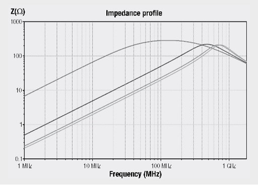
Fig. 1.58: Simulated array of curves for the impedance of SMD ferrite 742 792 121
ABC of CLR: Chapter L Inductors
EMC ferrite equivalent circuits
EPCI licensed content by: Würth Elektronik eiSos, Trilogy of Magnetics, handbook printouts can be ordered here.
[one_third]
see the previous page:
Equivalent Circuits and Simulation Models – Circuit Types
[/one_third][one_third]
< Page 8 >[/one_third][one_third_last]
see the next page:
Transformer: parasitic parameters and equivalent circuit
[/one_third_last]

This page content is licensed under a Creative Commons Attribution-Share Alike 4.0 International License.


