Passive Components Blog
No Result
View All Result
  • Home
  • NewsFilter
    • All
    • Aerospace & Defence
    • Antenna
    • Applications
    • Automotive
    • Capacitors
    • Circuit Protection Devices
    • electro-mechanical news
    • Filters
    • Fuses
    • Inductors
    • Industrial
    • Integrated Passives
    • inter-connect news
    • Market & Supply Chain
    • Market Insights
    • Medical
    • Modelling and Simulation
    • New Materials & Supply
    • New Technologies
    • Non-linear Passives
    • Oscillators
    • Passive Sensors News
    • Resistors
    • RF & Microwave
    • Telecommunication
    • Weekly Digest

    YAGEO Extends Automotive Tantalum Polymer Capacitors for AI and ADAS Controllers

    Knowles Introduces PP Film Capacitors for High‑Stress Power Electronics

    High‑Power Current Sensing with YAGEO PK Metal Current Sensors

    AI Data Centers Push Aluminium Capacitor Prices Higher

    Murata Releases 1210 Metal Terminal Common Mode Choke for 10Base‑T1S In‑Vehicle Ethernet

    DigiKey Ads 27,000 New In-Stock Parts and 104 Additional Suppliers in Q2 2026

    Würth Elektronik Coupled Inductors Harnessing Leakage Inductance in SEPIC, ZETA and Ćuk Converters

    Samsung Introduces Ultra‑compact, High‑Capacitance MLCCs for AI Edge and Wearable designs

    Knowles Presents Pulse Power Capacitors for Demanding MedTech, Industrial and Defense Applications

    Trending Tags

    • Ripple Current
    • RF
    • Leakage Current
    • Tantalum vs Ceramic
    • Snubber
    • Low ESR
    • Feedthrough
    • Derating
    • Dielectric Constant
    • New Products
    • Market Reports
  • VideoFilter
    • All
    • Antenna videos
    • Capacitor videos
    • Circuit Protection Video
    • Filter videos
    • Fuse videos
    • Inductor videos
    • Inter-Connect Video
    • Non-linear passives videos
    • Oscillator videos
    • Passive sensors videos
    • Resistor videos

    EMC Design Fundamentals: Safe Use of Varistors and Common Mode Chokes in Mains and Data-Line Filters

    Ferrite versus Nanocrystalline Power Inductor Cores: Turns, Gap and Size

    KYOCERA AVX Presents Antenna Integrator Studio Tutorial for Antenna Placement and RF Design

    Power Design Simulation Tools for Faster Inductor Selection and Loss Optimization

    EMC‑Compliant PCB and Connector Design Guidelines

    Why Isolated DC/DC Power Supplies Fail Late, Würth Elektronik Podcast

    Designing 800 V DC EMC Filters: Calculation, Simulation and Measurement

    Current Sense Transformer Datasheet and Design‑in Guide

    Designing a USB Type‑C Flyback Planar Transformer with Frenetic’s Planar Tool

    Trending Tags

    • Capacitors explained
    • Inductors explained
    • Resistors explained
    • Filters explained
    • Application Video Guidelines
    • EMC
    • New Products
    • Ripple Current
    • Simulation
    • Tantalum vs Ceramic
  • Knowledge Blog
  • Dossiers
    • AI Hardware Dossier
    • Power Converter Dossier
    • Automotive Dossier
    • Capacitor Dossier
    • Resistor Dossier
    • Inductor Dossier
    • Circuit Protection Dossier
  • Suppliers
    • Who is Who
  • PCNS
    • PCNS 2025
    • PCNS 2023
    • PCNS 2021
    • PCNS 2019
    • PCNS 2017
  • Events
  • Home
  • NewsFilter
    • All
    • Aerospace & Defence
    • Antenna
    • Applications
    • Automotive
    • Capacitors
    • Circuit Protection Devices
    • electro-mechanical news
    • Filters
    • Fuses
    • Inductors
    • Industrial
    • Integrated Passives
    • inter-connect news
    • Market & Supply Chain
    • Market Insights
    • Medical
    • Modelling and Simulation
    • New Materials & Supply
    • New Technologies
    • Non-linear Passives
    • Oscillators
    • Passive Sensors News
    • Resistors
    • RF & Microwave
    • Telecommunication
    • Weekly Digest

    YAGEO Extends Automotive Tantalum Polymer Capacitors for AI and ADAS Controllers

    Knowles Introduces PP Film Capacitors for High‑Stress Power Electronics

    High‑Power Current Sensing with YAGEO PK Metal Current Sensors

    AI Data Centers Push Aluminium Capacitor Prices Higher

    Murata Releases 1210 Metal Terminal Common Mode Choke for 10Base‑T1S In‑Vehicle Ethernet

    DigiKey Ads 27,000 New In-Stock Parts and 104 Additional Suppliers in Q2 2026

    Würth Elektronik Coupled Inductors Harnessing Leakage Inductance in SEPIC, ZETA and Ćuk Converters

    Samsung Introduces Ultra‑compact, High‑Capacitance MLCCs for AI Edge and Wearable designs

    Knowles Presents Pulse Power Capacitors for Demanding MedTech, Industrial and Defense Applications

    Trending Tags

    • Ripple Current
    • RF
    • Leakage Current
    • Tantalum vs Ceramic
    • Snubber
    • Low ESR
    • Feedthrough
    • Derating
    • Dielectric Constant
    • New Products
    • Market Reports
  • VideoFilter
    • All
    • Antenna videos
    • Capacitor videos
    • Circuit Protection Video
    • Filter videos
    • Fuse videos
    • Inductor videos
    • Inter-Connect Video
    • Non-linear passives videos
    • Oscillator videos
    • Passive sensors videos
    • Resistor videos

    EMC Design Fundamentals: Safe Use of Varistors and Common Mode Chokes in Mains and Data-Line Filters

    Ferrite versus Nanocrystalline Power Inductor Cores: Turns, Gap and Size

    KYOCERA AVX Presents Antenna Integrator Studio Tutorial for Antenna Placement and RF Design

    Power Design Simulation Tools for Faster Inductor Selection and Loss Optimization

    EMC‑Compliant PCB and Connector Design Guidelines

    Why Isolated DC/DC Power Supplies Fail Late, Würth Elektronik Podcast

    Designing 800 V DC EMC Filters: Calculation, Simulation and Measurement

    Current Sense Transformer Datasheet and Design‑in Guide

    Designing a USB Type‑C Flyback Planar Transformer with Frenetic’s Planar Tool

    Trending Tags

    • Capacitors explained
    • Inductors explained
    • Resistors explained
    • Filters explained
    • Application Video Guidelines
    • EMC
    • New Products
    • Ripple Current
    • Simulation
    • Tantalum vs Ceramic
  • Knowledge Blog
  • Dossiers
    • AI Hardware Dossier
    • Power Converter Dossier
    • Automotive Dossier
    • Capacitor Dossier
    • Resistor Dossier
    • Inductor Dossier
    • Circuit Protection Dossier
  • Suppliers
    • Who is Who
  • PCNS
    • PCNS 2025
    • PCNS 2023
    • PCNS 2021
    • PCNS 2019
    • PCNS 2017
  • Events
No Result
View All Result
Passive Components Blog
No Result
View All Result

Filter Shape Factor and Selectivity

2.5.2025
Reading Time: 7 mins read
A A

This blog article from Knowles Precision Devices written by Peter Matthews explains basics on filter selection – filter shape factor and selectivity.

An Ideal Filter

The Ideal Filter would have unit gain (0dB) in its pass band and a gain of zero (-infinity dB) in its stop band. Between pass band and stop band there would be no indecision and would transition from 0dB to -infinity dB asymptotically.

RelatedPosts

Knowles Introduces PP Film Capacitors for High‑Stress Power Electronics

Knowles Presents Pulse Power Capacitors for Demanding MedTech, Industrial and Defense Applications

RF Filters and Passive Components Enabling the 7 Missile RF Subsystems

It would pass only the required frequencies without adding or subtracting anything from the signal and like a very discrete and fastidious butler we would not see it – just its perfect management of the frequencies in its care.

Sadly we cannot have perfect filters in the real word and so we compromise and accept some amount of non-unity gain in the pass band (insertion loss and pass band ripple) and non-zero gain in the stop band (finite stop band attenuation and stop band ripple).

In addition, there is some transition from pass band to stop band that needs to be understood and managed. This Transition Band can be a defining characteristic in the usefulness of a filter for a given application, and is talked about using the terms Shape Factor and Selectivity.
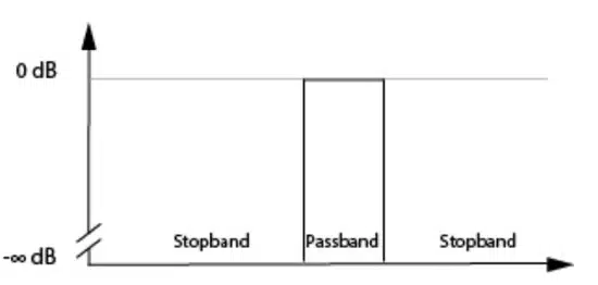
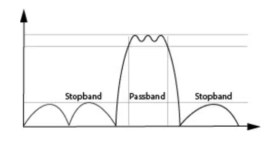
Figure 1. Ideal filter characteristic
Figure 2. Real filter characteristic

Filter Shape Factor

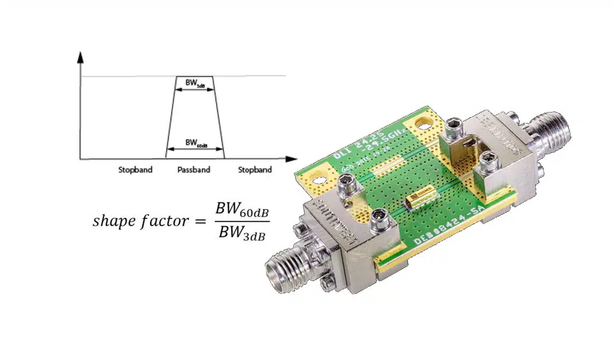
Usually the shape factor is defined as shown in Figure 3 (which shows an otherwise ideal filter with just the addition of transition bands) and equation 1.
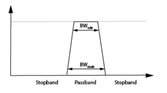
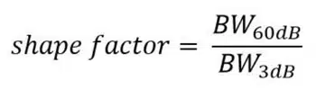
Figure 3. Filter shape factor
Equation 1. Filter shape factor calculation

The transition band characteristics we are usually interested in deal with the shape or steepness of the roll-off between the pass band and the stop band. Usually the shape factor is defined as shown in Figure 3 (which shows an otherwise ideal filter with just the addition of transition bands) and equation 1. It is defined for two levels of attenuation, and is usually taken to be the ration between 3dB of attenuation (pass band) and a given stop band attenuation.

For example, we could take 3dB to define the pass band and 60dB to use the stop band, and then use equation 1 to calculate shape factor. Our ideal filter would have a shape factor of unity, but where this is not physically realizable we seek the smallest shape factor we can. For reference simple RLC filters might have shape factors in the range of ~3, SAW filters in the range of ~1.5.

Selectivity

Shape factor is a common figure of merit for a related term, selectivity. For an RF filter selectivity tells us how much of the total bandwidth will be used by transition bands. The smaller the transition bands the smaller any necessary guard bands can be and less of the bandwidth is wasted in this way.

Selectivity is also discussed in terms of the steepness of the filter skirts and is often characterized in terms of so many dB of attenuation from the pass band at a given offset. In this we can begin to see how a filters selectivity can be a critical specification when it comes to its suitability for a given application, since often a systems transmission and reception characteristics are given in terms of not just insertion loss in the pass band but clearly prescribed attenuation requirements in the stop band.

The selectivity of a filter is closely related to the both the Q factor of a filter and the complexity of a filter (in terms of order).

Q Factor and Selectivity

The q factor of a filter can be defined as:
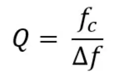
Equation 2. Filter Q factor calculation

As we reduce the bandwidth of our filter Q increases, the skirts become steeper and our filter becomes more selective. A band pass filter increases in selectivity as Q increases.

Filter Order and Selectivity

The number of resonators (n) used in a filter design defines the filter order.
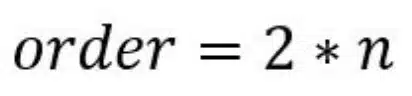
Equation 3. Filter order definition

In general we can design for steeper skirts (a “sharper filter”) with higher order filter designs, but at the cost of increased insertion loss and filter size.

Using filter technology that is inherently high Q to begin with is beneficial for high selectivity designs, since to the Q (and low insertion loss that comes with this) can be balanced against the necessary order of the design that would otherwise be required to hit a given selectivity target. This is why acoustic wave filters (e.g. SAW and BAW) have been so popular at frequencies below 2GHz – at those frequencies the physics of containing an acoustic wave inside a small package leads to very high Q factors and as a consequence excellent selectivity at the frequencies where SAW and BAW perform well.

Selectivity of Receivers

Applied to systems, selectivity is a receiver’s ability to discriminate between signals having different frequencies. Selectivity is often expresses as a ration in dB that compares the signal strength received with that of a similar signal at a different frequency. Depending on the location of the other (unwanted) signal relative to the desired signal, and the type of standard being discussed selectivity can be discussed as adjacent channel rejection (ACR), adjacent channel selectivity (ACS), in-band blocking and out of band blocking.

The need for selectivity in a receiver and the ability of available filters to deliver that can strongly influence receiver architecture. Selectivity can be obtained with suitable filters at the RF stage of a receiver, but if the bandwidth and stop band attenuation requirements cannot be met with an RF filter another option is to down convert the signal and implement high selectivity at the IF stage such as in a super heterodyne receiver. This approach however necessitates image rejection filters – so the ability to achieve reasonable levels of selectivity at RF can simplify architecture choices. In fact sufficiently high selectivity close to the antenna can significantly simplify the demodulation electronics downstream.

In this short introduction to Shape Factor and Selectivity, we have seen how real-world filter deviation from ideal behavior needs to be quantified and that in the transition band, common tools to do that are shape factor and selectivity. We have touched on how both resonator Q and the filter order (number of resonators in a design) can influence a filters behavior in the transition band. And we have seen how the topic of selectivity can expand out to influence the behavior and complexity of a receiver and how well it can perform relative to system level specifications such as ACR and ACS.


Related

Source: Knowles Precision Devices

Recent Posts

Bourns Introduces LTCC Band Pass Filters for 5G C‑Band RF Front‑End Designs

29.7.2026
14

Bourns Introduces LTCC GNSS L‑Band Diplexer for Compact RF Front Ends

24.7.2026
27

RF Filters and Passive Components Enabling the 7 Missile RF Subsystems

9.7.2026
83

Designing 800 V DC EMC Filters: Calculation, Simulation and Measurement

4.6.2026
316

Qi2 Wireless Charging: Inductors, Capacitors and EMC Filters

21.5.2026
147

TDK Releases Ultra‑small EMI Noise Suppression Filters

8.4.2026
61

Kyocera Offers Small SAW Filters for IoT RF Modules

23.2.2026
64

Transient Suppression Guide

22.5.2026
1.2k

Overvoltage and Transient Protection for DC/DC Power Modules

13.11.2025
469

Upcoming Events

Sep 29
16:00 - 17:00 CEST

Cybersecurity 2026

View Calendar

Popular Posts

  • Buck Converter Design and Calculation

    0 shares
    Share 0 Tweet 0
  • Boost Converter Design and Calculation

    0 shares
    Share 0 Tweet 0
  • YAGEO Announces July 2026 Capacitor Price Increase

    0 shares
    Share 0 Tweet 0
  • Flyback Converter Design and Calculation

    0 shares
    Share 0 Tweet 0
  • LLC Resonant Converter Design and Calculation

    0 shares
    Share 0 Tweet 0
  • MLCCs in the Age of AI: Q2 2026 Market Tightness

    0 shares
    Share 0 Tweet 0
  • MLCC and Ceramic Capacitors

    0 shares
    Share 0 Tweet 0
  • Earthing Systems and IEC Classification Explained

    0 shares
    Share 0 Tweet 0
  • Dual Active Bridge (DAB) Topology

    0 shares
    Share 0 Tweet 0
  • Core Materials, Permeability and Their Losses

    0 shares
    Share 0 Tweet 0

Newsletter Subscription


Passive Components Blog

© EPCI - Leading Passive Components Educational and Information Site

  • Home
  • Privacy Policy
  • EPCI Membership & Advertisement
  • About

No Result
View All Result
  • Home
  • Knowledge Blog
  • Dossiers
  • PCNS

© EPCI - Leading Passive Components Educational and Information Site