This article based on Knowles Precision Devices blog explains role and function of filter in radar receivers application.
In the article RF Components for Radar Application, we provided an overview of the key functional units in radar, including duplexing, filtering, power amplification, waveform generation, low-noise amplification (LNA), receiving, and analog-to-digital conversion (ADC). While in the third installment we talked about filtering in terms of switch filter banks, in this post we will dive more into the jobs filters must perform in radar receivers.
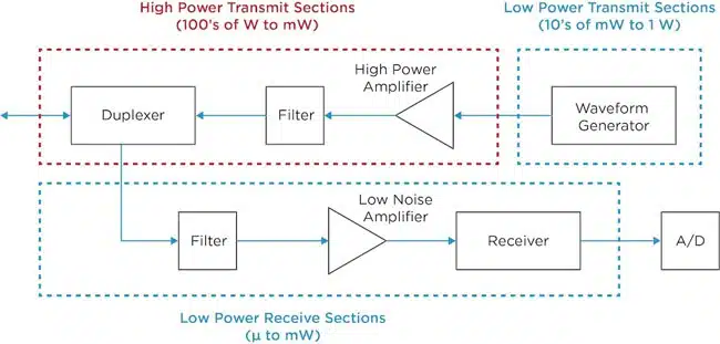
In general, filters are responsible for solving a variety of problems in the radar receiver. You can think of a filter as the problem-solving assistant in the system that comes along and tidies up different messes that are either outside the radar or made by components in the radar itself. Take a look at the radar functions diagram we discussed in the beginning of the series (Figure 1) and think about the receiver.
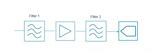
A typical heterodyne receiver has several filter jobs that need to be done, depending on the problems that need to be solved/messes that need to be cleaned up (Figure 2). Let’s take a closer look at these problems and the filtering technology that can be used to solve them.
Solving Signal Problems in a Radar Receiver with Filtering
In the radar receiver, the first problem that must be solved is selecting the band of interest and removing any signals outside the band of interest that would confuse or overwhelm the receiver – this is what the first filter must take care of. The second problem to be solved is to remove any signals close enough to the band of interest that exist at mixer image. The second filter takes care of these mixer related messes.
The third set of problems then arise when we get to the ADC. Here we need to remove any messes made by the amplifier and ensure the ADC only “sees” the correct alias band. A high-rejection filter close to the ADC can take care of this. In the case of the heterodyne approach, this job can be made easier by making the intermediate frequency (IF) fall well below the ADC’s Nyquist limit (which defines the maximum frequency that can be accurately captured and represented without distortion when using a specific sampling rate).
With recent ADC technology innovations, it is now possible to perform direct sampling up to X band frequencies, depending on the sensitivity required. Since direct sampling digitizes signals directly, the mixer and some of the amplifiers in the receiver can be removed (Figure 3), eliminating some of the messes the filters need to clean up.
What we are left with when a direct sampling receiver is used is problem 1 – selecting the correct band of interest and removing out of band interference – and problem 3 – cleaning up the interference generated by the amplifier and selecting the alias bands of the ADC. We’ve effectively eliminated problem 2. Depending on the performance required in the receiver, and the RF input to the ADC, a high rejection level may be required to achieve this. For example, in an X band direct sampling system, you may see a broadband, low-loss, and high-rejection filter such as our B096QC2S in this role.
As direct sampling receivers evolve, fully digital beamforming becomes realistic at some of the key radar bands such as S and X and eventually Ka. Knowles’ filter technology is rapidly advancing to keep pace with these possibilities.


