• Latest
  • Trending
  • All
  • Capacitors
  • Resistors
  • Inductors
  • Filters
  • Fuses
  • Non-linear Passives
  • Applications
  • Integrated Passives
  • Oscillators
  • Passive Sensors
  • New Technologies
  • Aerospace & Defence
  • Automotive
  • Industrial
  • Market & Supply Chain
  • Medical
  • RF & Microwave
  • Telecommunication

Basic Filter Circuits Explained

4.1.2023

Supercapacitors for Space Applications: Trends and Opportunities

3.1.2023

JX Nippon Mining and Metals Announces Participation in Tantalum Production at Mibra Mine in Brazil

30.12.2022

A Pitfall of Transformer-Based Isolated DC-DC Converter

30.12.2022

Best Wishes for 2023 from EPCI

29.12.2022

Kyocera Doubling its Investment into Electronic Components over the Three Years

29.12.2022

Leakage Models of Multi-Winding Transformer in LLC Converter

28.12.2022
  • Home
  • Privacy Policy
  • EPCI Membership & Advertisement
  • About
No Result
View All Result
NEWSLETTER
Passive Components Blog
  • Home
  • NewsFilter
    • All
    • Aerospace & Defence
    • Antenna
    • Applications
    • Automotive
    • Capacitors
    • Filters
    • Fuses
    • Inductors
    • Industrial
    • Integrated Passives
    • Market & Supply Chain
    • Medical
    • New Materials & Supply
    • New Technologies
    • Non-linear Passives
    • Oscillators
    • Passive Sensors
    • Resistors
    • RF & Microwave
    • Telecommunication

    Supercapacitors for Space Applications: Trends and Opportunities

    JX Nippon Mining and Metals Announces Participation in Tantalum Production at Mibra Mine in Brazil

    A Pitfall of Transformer-Based Isolated DC-DC Converter

    Kyocera Doubling its Investment into Electronic Components over the Three Years

    Leakage Models of Multi-Winding Transformer in LLC Converter

    Murata is Looking for Partners to Develop Applications of its New Transparent and Bendable Conductive Film

    LLC Transformer Design for Power Converters

    Printed Resistors in a High Performance PCB System

    Transformer Leakage in LLC converters

    Trending Tags

    • Ripple Current
    • RF
    • Leakage Current
    • Tantalum vs Ceramic
    • Snubber
    • Low ESR
    • Feedthrough
    • Derating
    • Dielectric Constant
    • New Products
    • Market Reports
  • VideoFilter
    • All
    • Antenna videos
    • Capacitor videos
    • Filter videos
    • Fuse videos
    • Inductor videos
    • Non-linear passives videos
    • Oscillator videos
    • Passive sensors videos
    • Resistor videos
    • Sensors

    A Pitfall of Transformer-Based Isolated DC-DC Converter

    Leakage Models of Multi-Winding Transformer in LLC Converter

    LLC Transformer Design for Power Converters

    Printed Resistors in a High Performance PCB System

    Transformer Characteristics Explained

    Variable Controlled Inductor in LLC Converter Application Example

    Vishay Presents Pulse Energy Calculator

    Magnetic Circuits LTSpice Modelling Part II.

    How to Design an Inductor; Frenetic Webinar

    Trending Tags

    • Capacitors explained
    • Inductors explained
    • Resistors explained
    • Filters explained
    • Application Video Guidelines
    • EMC
    • New Products
    • Ripple Current
    • Simulation
    • Tantalum vs Ceramic
  • Knowledge Blog
  • Suppliers
    • Preferred Suppliers
    • Who is Who
  • Events
No Result
View All Result
Passive Components Blog
No Result
View All Result

Basic Filter Circuits Explained

4.1.2023
Reading Time: 8 mins read
0 0
0
SHARES
458
VIEWS

This article published by Knowles Precision Devices Blog explains some basic filter circuit background information on how filters do what they do.

Regardless of the technology behind the filter, there are several key concepts that all filters share that we will dive into throughout this series.

RelatedPosts

The Benefits of Using MLCCs in Converters

Cavity Resonator Filters Basics

To Be COTS for Space or Not to Be ?

At the most basic level, filters are necessary in RF devices so that unwanted frequencies do not pass through the circuit and cause interference. While filtering can become quite complex as operating frequencies increase, it can be made much less daunting by having an understanding of how basic filters are built using standard electrical components such as resistors (Rs), capacitors (Cs), and inductors (Ls).

Before we jump into types of filters though, let’s start by looking at how a voltage divider functions. A voltage divider is a passive linear circuit that produces an output voltage (Vo) that is a fraction of the input voltage (Vi). As shown in Figure 1, the voltage divider changes the Vi down to the Vo based on the values of the resistors used, which are R1 and R2 below.

Figure 1. An illustration of the very familiar DC circuit, the voltage divider.

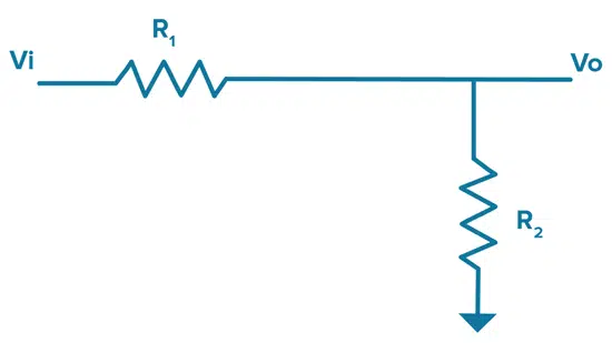
If we start with Ohms Law, which as a reminder, states that electric current is proportional to voltage and inversely proportional to resistance since resistance hinders the flow of current in the circuit, we can derive the following formula for how a voltage divider works:

voltage divider equation [1]

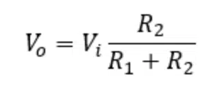
As you can see from the formula above, as R1 grows (or as R2 shrinks) the output voltage will drop.

Swapping Rs and Cs to Turn Our Voltage Divider into a Filter

Now that we know how our simple voltage divider works, let’s look at what happens if we trade out some Rs for Cs. Impedance of a capacitor will change with frequency and that capacitance can be calculated as follows:
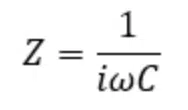
capacitance (capacitive impedance) equation [2]
  • Z = Impedance
  • Omega = Angular Frequency
  • i is the imaginary number since we are using complex numbers here
  • C = Capacitance

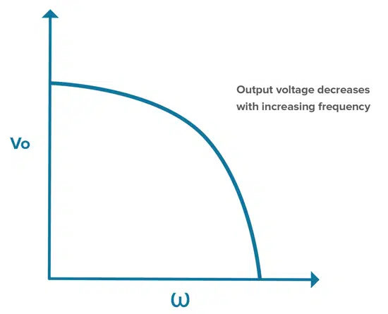
Thus, for a capacitor, impedance decreases with frequency. So, if we swap R2 for a C as shown in Figure 2, we will have a low-pass RC filter, which is a filter circuit that passes frequency signals below a certain cutoff frequency and blocks frequency signals higher than that point.

RC Low Pass Filter

In the RC low-pass filter, the path to ground goes through a capacitor, which means impedance will decrease with increasing frequency. Therefore, in this circuit, the ratio of the Vi down to the Vo will depend on the values of R and C and the frequency of the signal. With high frequencies, impedance is low and energy is sent to ground as Vi is divided down. Low frequencies see a higher impedance and energy is sent to the output.

Figure 2. A diagram of an RC low-pass filter.
Figure 3. Output voltage decreases with increasing frequency in an RC low-pass filter.

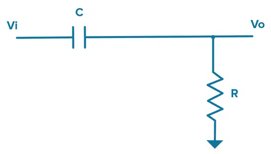
If we do this the other way around and replace R1 with a C, the path to output goes through the capacitor and we get the opposite effect.

RC High Pass Filter

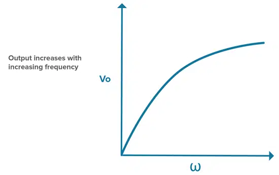
In this configuration, low frequencies see impedance that is higher than R, so the low-frequency signals go to ground while the high-frequency signals see an impedance lower than R, which means we get a high-frequency output.

Figure 4. A diagram of an RC high-pass filter.
Figure 5. Output voltage increases with increasing frequency when using a high-pass RC filter.

Swapping Cs and Ls to Create Your Desired Filter

Inductors have the opposite response to frequency than capacitors. This can be calculated as follows:
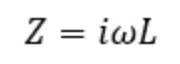
inductance (inductive impedance) equation [3]

L = Inductance

This means that impedance increases with frequency in an inductor. To create a low-pass filter using an R and L, we can start with an RC high-pass filter as shown in Figure 4 and swap the C for an L. We can also take the same type of approach to design a high-pass filter if we start with a RC low-pass filter as shown in Figure 2 and replace the C with an L. Both examples are illustrated in Figure 6.

Figure 6. In the top diagram, a low-pass filter is converted to a high-pass filter by swapping the C for an L in the path to ground. In the bottom diagram, the high-pass filter is converted to a low-pass filter by swapping the C for an L in the output line.

As it turns out, RC filters don’t provide the best performance in terms of roll off, which is the slope over frequency from passing a signal to blocking it. To improve this, RF designers can combine Cs and Ls, balancing their opposite responses to frequency to build different low-pass, high-pass, and band pass LC filter responses as shown in Figure 7.

Figure 7. Different types of LC filters and their frequency responses.

Manipulating Impedance to Achieve a Desired Frequency Response in Your Filter

Figure 8. In this example, L and C are replaced with impedances Z1 and Z2.

Given that Rs, Cs, and Ls offer different variations on impedance, we can think of designing a filter response as manipulating different impedances to achieve a desired frequency response. Thinking back to the DC voltage divider we started with at the beginning of this post, we can build on this to create a high pass circuit by adding networks of impedance (Zs) using various combinations of RCs and LCs as discussed throughout this post. Figure 8 below shows a high pass circuit where Z1 decreases with frequency and Z2 increases with frequency. In general, by replacing individual Rs, Cs, and Ls with sections of a circuit that have very specific impedance vs frequency behavior, we can create more complex high-performance filters.

By breaking down the different ways to use the frequency dependencies of Cs and Ls, you can see how it is possible to get a variety of different filter responses and form simple filters that can serve as the building blocks for more complex filtering needs.


Five key filter specifications to understand and check can be followed in related article here.

Source: Knowles Precision Devices

Related Posts

Aerospace & Defence

Supercapacitors for Space Applications: Trends and Opportunities

3.1.2023
15
Inductors

A Pitfall of Transformer-Based Isolated DC-DC Converter

30.12.2022
44
Inductors

Leakage Models of Multi-Winding Transformer in LLC Converter

28.12.2022
22

Upcoming Events

Jan 12
8:30 - 14:30 EST

Supercapacitor Virtual Technology Event; Richardson RFPD | EST

Jan 13
8:30 - 14:30 HKT

Supercapacitor Virtual Technology Event; Richardson RFPD | HKT

Jan 17
January 17 @ 12:00 - January 18 @ 14:00 CET

Microelectronic Packaging Failure Modes and Analysis

View Calendar

Popular Posts

  • Ripple Current and its Effects on the Performance of Capacitors

    3 shares
    Share 3 Tweet 0
  • Capacitor Selection for Coupling and Decoupling Applications

    28 shares
    Share 28 Tweet 0
  • What is a Dielectric Constant of Plastic Materials ?

    4 shares
    Share 4 Tweet 0
  • Understanding High-Precision Resistor Temperature Coefficient of Resistance

    0 shares
    Share 0 Tweet 0
  • Why Low ESR Matters in Capacitor Design

    0 shares
    Share 0 Tweet 0
  • How to Choose the Right Inductor for DC-DC Buck Applications

    0 shares
    Share 0 Tweet 0
  • Leakage Current Characteristics of Capacitors

    0 shares
    Share 0 Tweet 0
  • Coefficient of Linear Thermal Expansion on Polymers Explained

    0 shares
    Share 0 Tweet 0

Newsletter Subscription


Archive

2022
2021
2020
2019
2018
2017

Symposium

Passive Components Networking Symposium

Passives e-Learning

Knowledge Blog

  • Home
  • Privacy Policy
  • EPCI Membership & Advertisement
  • About

© EPCI - Premium Passive Components Educational and Information Site

No Result
View All Result
  • Home
  • News
  • Video
  • Knowledge Blog
  • Preferred Suppliers
  • Events

© EPCI - Premium Passive Components Educational and Information Site

Welcome Back!

Login to your account below

Forgotten Password?

Retrieve your password

Please enter your username or email address to reset your password.

Log In
This website uses cookies. By continuing to use this website you are giving consent to cookies being used. Visit our Privacy and Cookie Policy.