Passive Components Blog
No Result
View All Result
  • Home
  • NewsFilter
    • All
    • Aerospace & Defence
    • Antenna
    • Applications
    • Automotive
    • Capacitors
    • Circuit Protection Devices
    • electro-mechanical news
    • Filters
    • Fuses
    • Inductors
    • Industrial
    • Integrated Passives
    • inter-connect news
    • Market & Supply Chain
    • Market Insights
    • Medical
    • Modelling and Simulation
    • New Materials & Supply
    • New Technologies
    • Non-linear Passives
    • Oscillators
    • Passive Sensors News
    • Resistors
    • RF & Microwave
    • Telecommunication
    • Weekly Digest

    Samsung Electro-Mechanics Releases High-Capacitance MLCCs for AI Server Applications

    Samsung Electro-Mechanics Releases 165C Automotive 0806 Size Power Inductors

    Coupled Inductors Circuit Model and Examples of its Applications

    Würth Elektronik Introduces LTspice Models for ESD Products

    Capacitor Ripple Current Testing: A Design Consideration

    TDK Releases 0201 High-Frequency Smallest Inductors

    Coilcraft Extends Air Core RF Inductors

    Bourns Releases Automotive 1W Flyback Transformer

    Wk 20 Electronics Supply Chain Digest

    Trending Tags

    • Ripple Current
    • RF
    • Leakage Current
    • Tantalum vs Ceramic
    • Snubber
    • Low ESR
    • Feedthrough
    • Derating
    • Dielectric Constant
    • New Products
    • Market Reports
  • VideoFilter
    • All
    • Antenna videos
    • Capacitor videos
    • Circuit Protection Video
    • Filter videos
    • Fuse videos
    • Inductor videos
    • Inter-Connect Video
    • Non-linear passives videos
    • Oscillator videos
    • Passive sensors videos
    • Resistor videos

    Coupled Inductors Circuit Model and Examples of its Applications

    Inductor Resonances and its Impact to EMI

    Highly Reliable Flex Rigid PCBs, Würth Elektronik Webinar

    Causes of Oscillations in Flyback Converters

    How to design a 60W Flyback Transformer

    Modeling and Simulation of Leakage Inductance

    Power Inductor Considerations for AI High Power Computing – Vishay Video

    Coupled Inductors in Multiphase Boost Converters

    VPG Demonstrates Precision Resistor in Cryogenic Conditions

    Trending Tags

    • Capacitors explained
    • Inductors explained
    • Resistors explained
    • Filters explained
    • Application Video Guidelines
    • EMC
    • New Products
    • Ripple Current
    • Simulation
    • Tantalum vs Ceramic
  • Knowledge Blog
  • Suppliers
    • Who is Who
  • Events
No Result
View All Result
Passive Components Blog
No Result
View All Result

High Vibration Acceleration-Resistant, Power Choke Coil for Automotive Use

3.6.2019
Reading Time: 4 mins read
A A

Source: Panasonic article

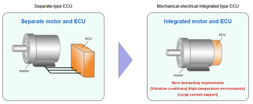
With the growing demand for energy efficiency of eco-friendly cars and the need to comply with environmental regulation, computerization of cars has been rapidly expanding, and ECUs are being incorporated, more frequently and on larger scales in cars. In addition, more ECUs are being placed within the engine itself, elevating integration of mechanical and electronic in-vehicle components. This trend has created a need for automotive ECUs that can be installed in high-temperature environments that have more severe vibration conditions and support large current.

RelatedPosts

Samsung Electro-Mechanics Releases High-Capacitance MLCCs for AI Server Applications

Samsung Electro-Mechanics Releases 165C Automotive 0806 Size Power Inductors

Coupled Inductors Circuit Model and Examples of its Applications

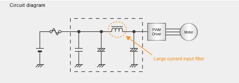
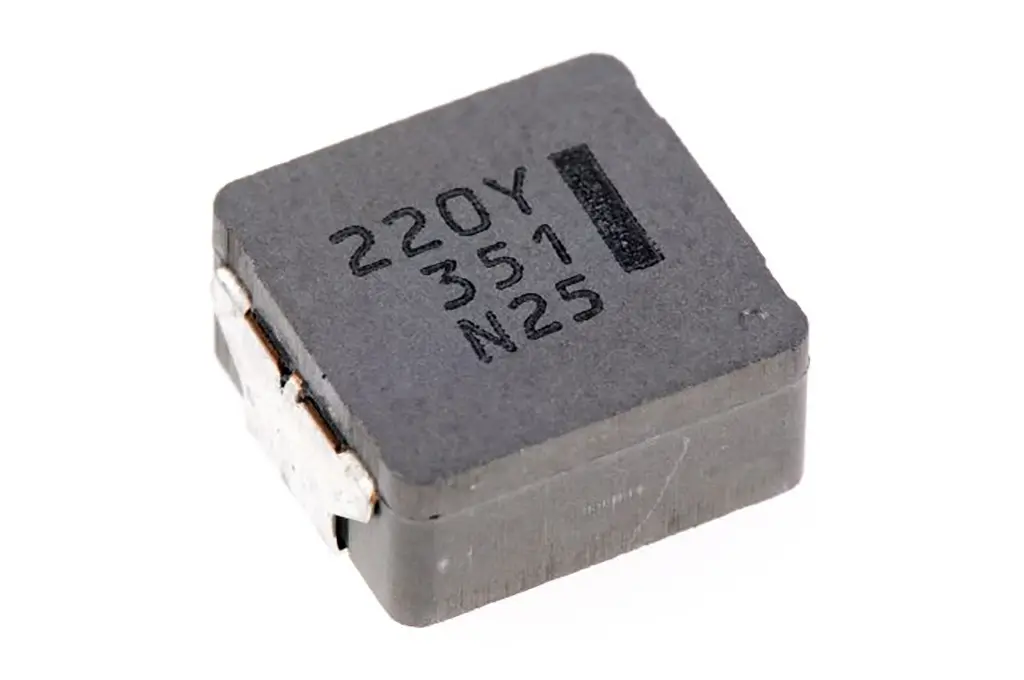
Choke coils with high resistance to vibration and heat as well as support for large current are essential for removing noise and smoothing the power supply of power circuits that constitute automotive ECUs. Panasonic is launching its surface-mounted type power choke coil for automotive use achieving resistivity of 50 G or higher vibration acceleration.

What is high vibration acceleration-resistant, power choke coil for automotive use 

Excellent vibration resistance, heat resistance, and large current support allow customers to streamline their production process, and contribute to the placement of ECUs in the engine itself and integration of mechanical and electrical components.

Features of high vibration acceleration-resistant, power choke coil for automotive use 

  1. High resistance to vibration acceleration, enabling the automotive ECU to be more resistant to vibration.
  2. Remove the need for the anti-vibration reinforcement as part of the board mounting process, allowing the streamlining of the production process.
  3. Its excellent heat-resistance and support for large current, contributes to the ability to place of automotive ECUs in the engine itself.

Product Features

1. The power choke coil has high resistance to vibration acceleration, enabling automotive ECUs to be more resistant to vibration.

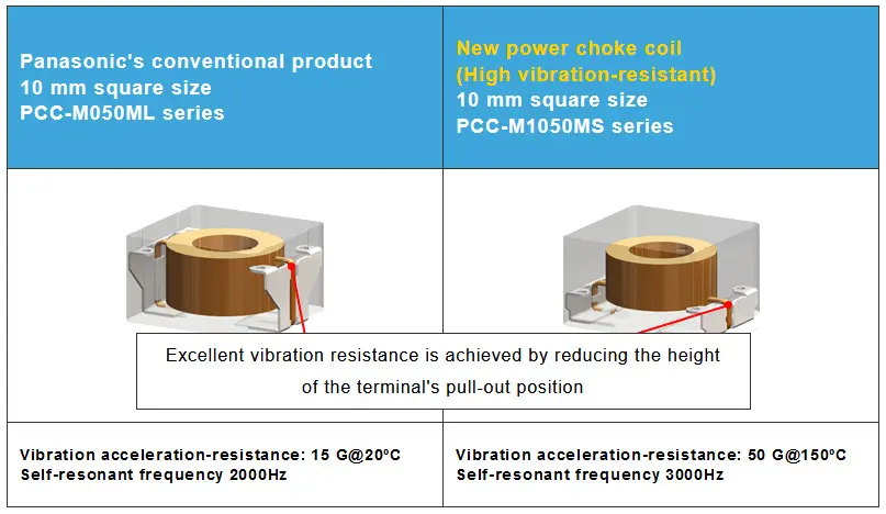
The new power choke coil withstands vibration acceleration of 50 G or higher in 150ºC environments (490 m/s2). The conventional product only withstands vibration acceleration of 15 G (147 m/s2).

Conventional products structurally have a low self-resonant frequency around 2,000 Hz and have an issue with vibration resistance. By utilizing the company’s unique metal composite material using its unique metal magnetic material and unique winding and molding technologies, Panasonic created a coil with a high self-resonant frequency of 3,000 Hz or higher leading to high resistance to vibration acceleration of 50 G or higher, contributing to more vibration-resistant automotive ECUs.

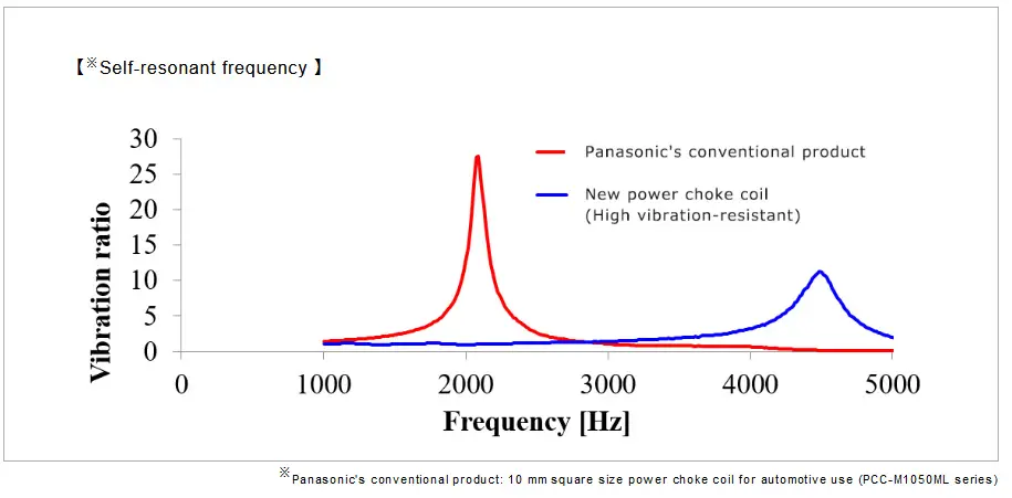
Self-resonant frequency:
An inductor has a natural frequency, and this frequency is referred to as self-resonant frequency. When the frequency of vibration conditions externally applied is in vicinity of the self-resonant frequency, stress several to several tens of times of applied acceleration is applied on the inductor, significantly deteriorating the vibration resistance.

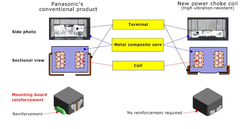
2. The new power choke coil removes the need for anti-vibration reinforcement as part of the board mounting process, allowing the streamlining of the production process

The conventional automotive ECU board mounting process requires anti-vibration measures, such as anchoring components with bonding agents (adhesives), to make the ECU resistant to vibration. The height of the developed power choke coil’s terminal pull-out position is reduced to half that of the company’s conventional product through the adoption of the company’s unique winding and molding technologies, allowing its placement near the mounting board and achieving excellent vibration resistance. This has made conventional anti-vibration measures unnecessary, and allowing the streamlining of the production process.

3.The power choke coil, with their excellent heat-resistance and support for large current, contributes to the placement of automotive ECUs within the engine itself

Coils used in automotive ECUs are required to be heat-resistant and support high current, in addition to being highly resistant to vibration. Previously, coils with high resistance to vibration acceleration of 30 G or higher had an issue of not being able to support large current due to their low profile and small size. The developed power choke coil achieves a vibration acceleration resistance of 50 G or higher while also having excellent heat resistance and supporting large current, through the adoption of the company’s unique metal composite material, thereby contributing to the placement of automotive ECUs in the engine itself.

【Vibration durability conditions】

Vibration acceleration 50G(490 m/s2)
Frequency 5~2000Hz
Amplitude 5mm max.
Vibration directions, number of times (Time) X, Y, Z directions, 108 times (equivalent to 100 h)
Temperature 150°C (including product’s self-heating when energized)

【Lineup】

Series Part No. Case size
(L×W)㎜
Inductance(※1) DC resistance
(at 20℃)(※2)
Rated current
(※3)
PCC-M1050MS ETQP5MR68YSC 10.9 x 10.0 0.68 µH 1.66 mΩ 27.0 A
PCC-M0854MS ETQP5M2R5YSK 8.5 x 8.0 2.45 µH 7.40 mΩ 12.0 A
  • (※1) Measured at 100 kHz.
  • (※2) Typical value
  • (※3) DC current which causes temperature rise of 40 K. Parts are soldered by reflow on four-layer PWB (1.6 mm FR4) and measured at room temperature.

Application

Applications that require high vibration resistance, high heat resistance, and large current support

  • ELECTRIC PUMP INPUT FILTER
  • ELECTRIC FAN MOTOR INPUT FILTER
  • DIRECT INJECTION INPUT FILTER / BOOST CHOKE
  • BREAKING SYSTEM INPUT FILTER
  • EGR INPUT FILTER
  • ELECTRIC COMPRESSOR INPUT FILTER
  • EPS INPUT FILTER
  • START&STOP BUCK-BOOST & INPUT/OUTPUT FILTER
  • BODY ELECTRIC SYSTEM INPUT FILTER

Related

Recent Posts

Samsung Electro-Mechanics Releases 165C Automotive 0806 Size Power Inductors

21.5.2025
13

Coupled Inductors Circuit Model and Examples of its Applications

21.5.2025
21

Capacitor Ripple Current Testing: A Design Consideration

21.5.2025
33

TDK Releases 0201 High-Frequency Smallest Inductors

20.5.2025
18

Coilcraft Extends Air Core RF Inductors

20.5.2025
11

Bourns Releases Automotive 1W Flyback Transformer

19.5.2025
14

Inductor Resonances and its Impact to EMI

16.5.2025
48

Highly Reliable Flex Rigid PCBs, Würth Elektronik Webinar

15.5.2025
27

Würth Elektronik Releases High Performance TLVR Coupled Inductors

15.5.2025
34

YAGEO Extends Rectangular Aluminum Electrolytic Capacitor Family

15.5.2025
53

Upcoming Events

May 28
16:00 - 17:00 CEST

Power Over Data Line

View Calendar

Popular Posts

  • Buck Converter Design and Calculation

    0 shares
    Share 0 Tweet 0
  • Boost Converter Design and Calculation

    0 shares
    Share 0 Tweet 0
  • Flyback Converter Design and Calculation

    0 shares
    Share 0 Tweet 0
  • LLC Resonant Converter Design and Calculation

    0 shares
    Share 0 Tweet 0
  • Flying Capacitors Explained

    0 shares
    Share 0 Tweet 0
  • How to Design an Inductor

    0 shares
    Share 0 Tweet 0
  • Dual Active Bridge (DAB) Topology Explained

    0 shares
    Share 0 Tweet 0
  • Ripple Current and its Effects on the Performance of Capacitors

    3 shares
    Share 3 Tweet 0
  • Capacitor Ripple Current Testing: A Design Consideration

    0 shares
    Share 0 Tweet 0
  • What is a Dielectric Constant and DF of Plastic Materials?

    4 shares
    Share 4 Tweet 0

Newsletter Subscription


Passive Components Blog

© EPCI - Leading Passive Components Educational and Information Site

  • Home
  • Privacy Policy
  • EPCI Membership & Advertisement
  • About

No Result
View All Result
  • Home
  • Knowledge Blog
  • Premium Suppliers

© EPCI - Leading Passive Components Educational and Information Site

This website uses cookies. By continuing to use this website you are giving consent to cookies being used. Visit our Privacy and Cookie Policy.
Go to mobile version