Passive Components Blog
No Result
View All Result
  • Home
  • NewsFilter
    • All
    • Aerospace & Defence
    • Antenna
    • Applications
    • Automotive
    • Capacitors
    • Circuit Protection Devices
    • electro-mechanical news
    • Filters
    • Fuses
    • Inductors
    • Industrial
    • Integrated Passives
    • inter-connect news
    • Market & Supply Chain
    • Market Insights
    • Medical
    • Modelling and Simulation
    • New Materials & Supply
    • New Technologies
    • Non-linear Passives
    • Oscillators
    • Passive Sensors News
    • Resistors
    • RF & Microwave
    • Telecommunication
    • Weekly Digest

    High Energy Density Polymer Film Capacitors via Molecular and Interfacial Design

    Bourns Releases High Clearance and Creepage 1500VDC Power Transformer

    KYOCERA AVX Expands Stacked MLCC Capacitors Offering

    Murata and QuantumScape Joint Development for Solid Batteries Ceramic Separators

    YAGEO Unveils Compact 3.6kW LLC Transformer for OBC EV Charging

    Over-Voltage Protection Clippers, Clampers, Snubbers, DC Restorers

    KYOCERA Releases Shielded Board-to-Board Connectors for Reliable EMI Protection

    Wk 41 Electronics Supply Chain Digest

    Samtec Expands Connector Severe Environment Testing Offering

    Trending Tags

    • Ripple Current
    • RF
    • Leakage Current
    • Tantalum vs Ceramic
    • Snubber
    • Low ESR
    • Feedthrough
    • Derating
    • Dielectric Constant
    • New Products
    • Market Reports
  • VideoFilter
    • All
    • Antenna videos
    • Capacitor videos
    • Circuit Protection Video
    • Filter videos
    • Fuse videos
    • Inductor videos
    • Inter-Connect Video
    • Non-linear passives videos
    • Oscillator videos
    • Passive sensors videos
    • Resistor videos

    Connector PCB Design Challenges

    Efficient Power Converters: Duty Cycle vs Conduction Losses

    Ripple Steering in Coupled Inductors: SEPIC Case

    SEPIC Converter with Coupled and Uncoupled Inductors

    Coupled Inductors in SEPIC versus Flyback Converters

    Non-Linear MLCC Class II Capacitor Measurements Challenges

    Percolation Phenomenon and Reliability of Molded Power Inductors in DC/DC converters

    Root Causes and Effects of DC Bias and AC in Ceramic Capacitors

    How to Calculate the Output Capacitor for a Switching Power Supply

    Trending Tags

    • Capacitors explained
    • Inductors explained
    • Resistors explained
    • Filters explained
    • Application Video Guidelines
    • EMC
    • New Products
    • Ripple Current
    • Simulation
    • Tantalum vs Ceramic
  • Knowledge Blog
  • Suppliers
    • Who is Who
  • PCNS
    • PCNS 2025
    • PCNS 2023
    • PCNS 2021
    • PCNS 2019
    • PCNS 2017
  • Events
No Result
View All Result
Passive Components Blog
No Result
View All Result

How can failures in vibration tests be avoided?

3.6.2019
Reading Time: 5 mins read
A A

Source: Alter Technology article

by María Teresa Rodríguez.

RelatedPosts

High Energy Density Polymer Film Capacitors via Molecular and Interfacial Design

Bourns Releases High Clearance and Creepage 1500VDC Power Transformer

KYOCERA AVX Expands Stacked MLCC Capacitors Offering

Vibration tests are important to check the reliability of the components/assemblies. These tests can be a headache and suppose a great cost if the design of the device and the fixing tool are not properly done. Simulation tools are the key to anticipate the problems reducing costs and lead times and doEEEt gives you access, in just one site, to components and specifications from different systems and space agencies

Introduction to Modal Analysis:

All objects have a natural frequency inherent to each object, at which they vibrate when they are subjected to certain external forces. When a force is applied at the object’s natural frequency, it goes into resonance, and a higher amplitude vibration response is created. This situation can cause a collapse of the object. To avoid resonance, the frequency applied should not be at or near the natural frequency of the device or element under test. If the forcing frequency cannot be changed, natural frequency needs to be modified. This can only be done by altering the mass or its stiffness.

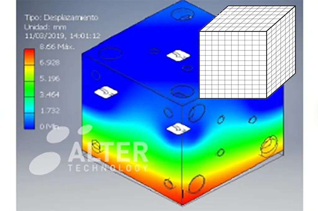
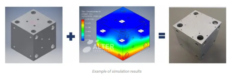
Simulation is used to validate the designs before manufacturing and testing phase in a laboratory. It is really useful to crosscheck the results of this analysis with the results obtained in the validation of the final assembly under the applicable vibration test and avoiding the resonance effect.

Vibration simulation, as others, is based in finite element analysis (FEA). The main goal of a modal analysis is to determinate the natural frequencies and vibration modes of an element during vibration. Usually to develop this type of analysis, Finite Elements Method (FEM) is used.

FEM is a method to solve differential equations and boundary value problems. It involves dividing a whole domain into simpler parts that are called finite elements.

A set of finite elements that make up the model to be simulated is called mesh. The mesh should be as regular and uniform as possible, and the size of the elements will depend on the precision needed to reproduce properly the geometry of the item to simulate. Once the model is ready, simulation tools proceed to the calculation and analysis of the results.


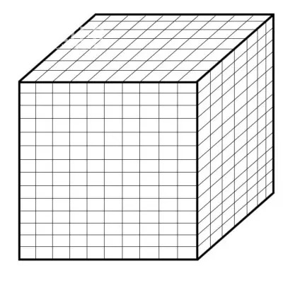
Example of a discretization model in finite elements


Step of a Correct Simulation:
To develop a correct simulation, it is necessary to follow the steps showed in the diagram below:

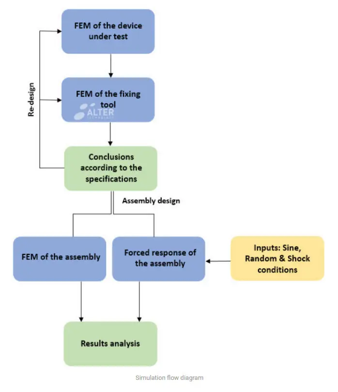
The success relies on the simulation of the natural frequencies of the DUT, the fixing tool and the assembly of both parts. The final simulation consists of the analysis of the forced response of the assembly under the conditions of the requirements. If any of the results fails, a re-design of any of the parts (the device, the fixing tool or the assembly) is required.

Requirements for the Simulation:

To perform all the simulations, the following information needs to be provided:

  • Materials and their mechanical properties of the fixing tools and the device under test (DUT). Also the surrounding elements, meaning the fitting interfaces of the tool with the shaker, in order to be able to do a proper model for the MEF analysis and to check with our vibration tool. This point is important because it may cause a big variation of the results due to the variation of the inner dynamics and damping of the DUT and are mainly known as boundary conditions.
  • Damping is a very important factor in the simulation. It is the way a system naturally dissipates energy. Its level cannot be studied by FEM. It is usually taken out by a Modal test. It can be used a value based on our experience in other projects or if it is necessary, we can use damping ranges in the FEM and see their effect.
  • By last, also is mandatory to know the full specification of the vibration profile. Sine, Random and/or Mechanical Shock vibration conditions. And their respective information, an axis of the vibration or the test which the information is related.

For vibration conditions, Alter Technology frequently tests according to the next specifications:

Title Reference Organization Parts
1 Generic Specification for Connectors Electrical Non-Filtered Circular and Rectangular ESCC 3401 European Space Components Coordination (ESCC) Connectors
7 High-reliability soldering for surface-mount and mixed technology ECSS-Q-ST-70-38C European Cooperation for Space Standardization (ECSS) Sodered system including Surface mounted devices (SMD), printed circuit boards (PCB)
10 Manual soldering of high-reliability electrical connections ECSS-Q-ST-70-08C European Cooperation for Space Standardization (ECSS) Sodered system including Surface mounted devices (SMD), printed circuit boards (PCB)
13 Test Method Standard, Microcircuits MIL-STD-883 TM2005 / TM2006 / TM2007 / TM2026 Defense and Logistic Agency Microcircuits
16 Test Methods for Semiconductor Devices MIL-STD-750 TM2016 TM2046 TM2051 TM2056 TM2057 MIL-STD-750 TM2016 / TM2046 / TM2051 / TM2056 / TM2057 Defense and Logistic Agency Semiconductors
19 Test Method Standard, Microcircuits MIL-STD-202 TM201 TM204 TM214 TM213 MIL-STD-202 TM201 / TM204 / TM214 / TM213 Defense and Logistic Agency Component parts

Related

Recent Posts

High Energy Density Polymer Film Capacitors via Molecular and Interfacial Design

15.10.2025
7

Bourns Releases High Clearance and Creepage 1500VDC Power Transformer

15.10.2025
2

KYOCERA AVX Expands Stacked MLCC Capacitors Offering

14.10.2025
11

YAGEO Unveils Compact 3.6kW LLC Transformer for OBC EV Charging

13.10.2025
111

Silicon Capacitors Market: Shaping the Foundation for Next-Gen Miniaturization Electronics

10.10.2025
33

YAGEO Releases Compact Coupled Inductors for High-Density VR Designs

9.10.2025
21

Enhancing Energy Density in Nanocomposite Dielectric Capacitors

9.10.2025
31

Advances in the Environmental Performance of Polymer Capacitors

8.10.2025
62

Vishay Releases DLA Tantalum Polymer Capacitors for Military and Aerospace

8.10.2025
26

Vishay Expanded Inductor Portfolio With More Than 2000 Stock Items 

8.10.2025
14

Upcoming Events

Oct 15
20:00 - 20:30 CEST

Planar Design & Simulation

Oct 17
12:00 - 14:00 EDT

External Visual Inspection per MIL-STD-883 TM 2009

Oct 20
October 20 - October 23

Digital WE Days 2025 – Virtual Conference

View Calendar

Popular Posts

  • Buck Converter Design and Calculation

    0 shares
    Share 0 Tweet 0
  • Boost Converter Design and Calculation

    0 shares
    Share 0 Tweet 0
  • Flyback Converter Design and Calculation

    0 shares
    Share 0 Tweet 0
  • LLC Resonant Converter Design and Calculation

    0 shares
    Share 0 Tweet 0
  • What is a Dielectric Constant and DF of Plastic Materials?

    4 shares
    Share 4 Tweet 0
  • Ripple Current and its Effects on the Performance of Capacitors

    3 shares
    Share 3 Tweet 0
  • SEPIC Converter Design and Calculation

    0 shares
    Share 0 Tweet 0
  • Dual Active Bridge (DAB) Topology Explained

    0 shares
    Share 0 Tweet 0
  • MLCC and Ceramic Capacitors

    0 shares
    Share 0 Tweet 0
  • Flying Capacitors Explained

    0 shares
    Share 0 Tweet 0

Newsletter Subscription


Passive Components Blog

© EPCI - Leading Passive Components Educational and Information Site

  • Home
  • Privacy Policy
  • EPCI Membership & Advertisement
  • About

No Result
View All Result
  • Home
  • Knowledge Blog
  • PCNS

© EPCI - Leading Passive Components Educational and Information Site

This website uses cookies. By continuing to use this website you are giving consent to cookies being used. Visit our Privacy and Cookie Policy.
Go to mobile version