• Latest
  • Trending
  • All
  • Capacitors
  • Resistors
  • Inductors
  • Filters
  • Fuses
  • Non-linear Passives
  • Applications
  • Integrated Passives
  • Oscillators
  • Passive Sensors
  • New Technologies
  • Aerospace & Defence
  • Automotive
  • Industrial
  • Market & Supply Chain
  • Medical
  • RF & Microwave
  • Telecommunication

How to choose a surface-mount inductor for a DC/DC converter

24.8.2022

Exploring the Benefits of High-Performance MLCC Capacitors for Aerospace and Defense

23.3.2023

Murata Establishes Joint Venture Company to Produce MLCC Raw Materials

23.3.2023

Examining the Influence of ESR and Ripple Current on Selecting the Suitable Capacitor

21.3.2023

SABIC Validates its 150°C Film Foil to Enable Adoption of Film Capacitors in SIC Power Modules

20.3.2023

Outlook of Passive Electronic Components Market for Oil & Gas Electronics in 2023

20.3.2023

Flying Capacitors Explained

17.3.2023
  • Home
  • Privacy Policy
  • EPCI Membership & Advertisement
  • About
No Result
View All Result
NEWSLETTER
Passive Components Blog
  • Home
  • NewsFilter
    • All
    • Aerospace & Defence
    • Antenna
    • Applications
    • Automotive
    • Capacitors
    • Circuit Protection Devices
    • Filters
    • Fuses
    • Inductors
    • Industrial
    • Integrated Passives
    • Market & Supply Chain
    • Medical
    • New Materials & Supply
    • New Technologies
    • Non-linear Passives
    • Oscillators
    • Passive Sensors
    • Resistors
    • RF & Microwave
    • Telecommunication

    Exploring the Benefits of High-Performance MLCC Capacitors for Aerospace and Defense

    Murata Establishes Joint Venture Company to Produce MLCC Raw Materials

    Examining the Influence of ESR and Ripple Current on Selecting the Suitable Capacitor

    SABIC Validates its 150°C Film Foil to Enable Adoption of Film Capacitors in SIC Power Modules

    Outlook of Passive Electronic Components Market for Oil & Gas Electronics in 2023

    Flying Capacitors Explained

    TDK Introduces Compact High-Current Chokes for Automotive and Industrial Applications

    ECIA NA February 2023 Electronic Components Sales Confirms Growth Trend

    Investigating Modeling Techniques of Class II Ceramic Capacitors Losses for High Voltage and Current Applications

    Trending Tags

    • Ripple Current
    • RF
    • Leakage Current
    • Tantalum vs Ceramic
    • Snubber
    • Low ESR
    • Feedthrough
    • Derating
    • Dielectric Constant
    • New Products
    • Market Reports
  • VideoFilter
    • All
    • Antenna videos
    • Capacitor videos
    • Filter videos
    • Fuse videos
    • Inductor videos
    • Non-linear passives videos
    • Oscillator videos
    • Passive sensors videos
    • Resistor videos
    • Sensors

    Investigating Modeling Techniques of Class II Ceramic Capacitors Losses for High Voltage and Current Applications

    Understanding Basics of Current Sense Resistors

    What Decoupling Capacitor Value To Use And Where To Place Them

    How to Measure Rated Current on Power Inductors

    LTspice Simulation of a Spark-Gap Circuit Protection Surge Arrester

    Approximate Inductor Design Using Two Alternative Cores

    1kW Phase Shift Full Bridge Converter Design and Simulation

    Multiphase Buck Trans-Inductor Voltage Regulator (TLVR) Explained

    Smart Power Distribution Unit Architecture and Inductor Losses

    Trending Tags

    • Capacitors explained
    • Inductors explained
    • Resistors explained
    • Filters explained
    • Application Video Guidelines
    • EMC
    • New Products
    • Ripple Current
    • Simulation
    • Tantalum vs Ceramic
  • Knowledge Blog
  • Suppliers
    • Preferred Suppliers
    • Who is Who
  • Events
No Result
View All Result
Passive Components Blog
No Result
View All Result

How to choose a surface-mount inductor for a DC/DC converter

24.8.2022
Reading Time: 6 mins read
0 0
0
SHARES
1.6k
VIEWS

Source: Electronic Products, Signal Transformer article

Understanding the basics of the switch-mode converter principle will help designers select the best inductor for their application. By Mitchell Rhine, director of engineering, Signal Transformer.

RelatedPosts

Integrated Bulk Acoustic Wave (BAW) Technology Explained – Texas Instruments and Mouser Electronics EE Journal Chalk Talk Video

Würth Elektronik Introduces Robust, Resilient, Mountable Radio Interference Suppression Choke

What is RFID? How RFID works? RFID Explained in Detail

Traditional linear voltage regulators have one major drawback: The voltage dropped across the pass transistor multiplied by the load current equals wasted power. The preferred option is often a switch-mode DC/DC converter, wherein the power transistors are continuously switching with a duty cycle that, with some additional filtering, delivers the required output voltage.

In this configuration, the transistor is either ON, involving no voltage drop, or OFF with no current passing. This means that the power dissipation tends to go down to zero when switching between states, yielding an efficiency of up to 95%, while linear converters typically deliver about 50%. Switching converters have another major advantage in that their topology means that they can operate in step-down (so-called “buck,”), step-up (“boost”), or invert (“buck-boost”) modes.

A basic understanding of the switch-mode converter principle is helpful in selecting the inductor required. This article will focus on just a few basic configurations, primarily on the very popular fixed-frequency buck converter operated in “continuous mode.”
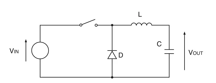
Fig. 1: A simple switching DC/DC converter.

A basic buck converter consists of just a switch, inductor, capacitor, and diode (Fig. 1). Assuming an ideal switch and diode, Vsw = 0 and Vd = 0, simplifies the explanation of the converter’s operation. In a real-world design case, to accurately determine the required inductance value L, the expected duty cycle D, and operating efficiency, Vsw and Vd have to be considered non-zero, and their effect on the converter circuit must be included.

When the switch is ON, the diode is off and a ramping current flows directly from input to output. When the switch is OFF, the voltage across the inductor reverses polarity due to its inductance attempting to keep the current flowing. This will turn on the “catch” diode, and this causes the current to ramp down until the switch turns on again and the cycle repeats. The ramping ON current increases the inductor core magnetization, storing energy in the inductor, which is returned during the OFF cycle as the current ramps down.
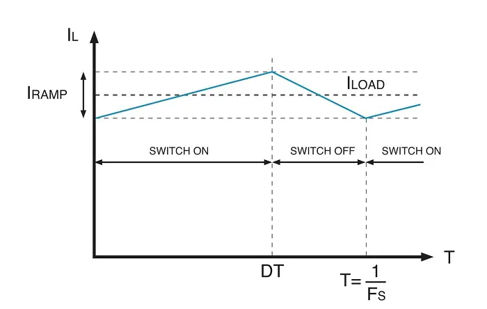
Fig. 2: The ramping waveform of a switching DC/DC converter.

The waveform of the current flowing through the inductor in the case of a buck converter is shown in Fig. 2. It includes an average DC component and an AC component, which is periodically ramping up and down. The DC current equals the DC load current Iload. Under steady-state conditions, the inductor current at the end of the cycle equals that at the start of the cycle.

The controlled switching action results in

Vout = D * Vin                                                                                       (Equation 1)

with D being the duty cycle as D = ton /(ton + toff).

The switching frequency is determined by fsw = 1/(ton + toff), with ton = D/fsw.

Adding up all the voltage drops generated in the circuit during ON time, and assuming that Vsw = 0, this results in

Vin – Vind – Vout= 0                                                                   (Equation 2)

If we now substitute Vind = L * di/dt, with di resembling the magnitude of the current ramp Iramp and dt the ON time ton, this will get us to

L * Iramp = (Vin – Vout) * ton                                                                    (Equation 3)

This has a significant consequence because the right hand side of Equation 3 is constant for a given input-to-output voltage difference, implying the same for the resulting switching frequency and the value of ton. A larger inductance value L equals a smaller ramping current component, while smaller inductance values will lead to a larger current ramp. Driving this to the extreme, if the inductance is chosen to be very small, there may be a current ramp so large that at a low-load current condition, the total current flowing through the inductor could drop to zero for part of the switching period. This condition is called discontinuous mode.

There is another important consideration that must be kept in mind; a smaller inductance, which may be attractive in some applications, leads to a larger inductor ramp current, and this causes a higher ripple to occur on the output voltage. A large Iramp also increases the AC core losses in the inductor. As a general guideline, Iramp should be small compared to the maximum load current; this determines the inductance value L for a given system design.

Now, let’s turn to a key specification in regard to choosing the proper inductance value. It is the maximum peak current through the inductor. In steady state operation, it is

Imax = Iload_max+ Iramp/2                                                             (Equation 4)

Looking at Equation 3, it is apparent that Iramp is independent of Iload. To determine Imax, a more detailed consideration is needed as to how Iramp will vary with different values of Vin after deciding on the values of the inductor L.

Adding up all the voltage drops and with Vd = 0 during OFF time, this results in

Vind – Vout = 0                                                                           (Equation 5)

Considering Vind = L * di/dt, with di being the magnitude of the current ramp Irampand dt being the OFF time toff, leads us to

Iramp = Vout * toff/L                                                                                (Equation 6)

If Vout is constant, Iramp is at a maximum when toff is also at a maximum. This occurs when Vin is at a maximum, and this condition determines Iramp and the maximum peak inductor current (Equation 4).

With the inductance value determined and the maximum current known, this finally leads us to the selection of the appropriate inductor type. Shielded and low-EMI inductors are good choices for densely populated boards, as is the case in new IoT designs. Their advantage is that their magnetic flux is contained within the inductor body, resulting in a lower radiation impact on surrounding PCB traces and components.

As an example, Signal Transformer’s SCRH series of magnetically shielded parts are available with inductance values ranging from 1.0 µH to 180 µH, saturation currents from 0.15 A to 5.0 A, and heights from 1.9 mm to 4 mm. If a larger inductance value is required, the SCxxxxC Series offers values from 10 µH to 1 mH, with saturation currents from 0.045 A to 8 A and heights from 2.92 mm to 7.62 mm. Other series are available for high-current applications as well as unshielded inductors for highest efficiency and robust power handling that include low-profile dimensions.

featured image source: Signal Transformer


Related Posts

Capacitors

Examining the Influence of ESR and Ripple Current on Selecting the Suitable Capacitor

21.3.2023
79
Market & Supply Chain

Outlook of Passive Electronic Components Market for Oil & Gas Electronics in 2023

20.3.2023
24
Capacitors

Flying Capacitors Explained

17.3.2023
46

Upcoming Events

Mar 19
March 19 - March 23

APEC 2023

Apr 3
April 3 @ 12:00 - April 4 @ 14:00 CEST

Microelectronic Packaging Failure Modes and Analysis

Apr 5
11:00 - 12:00 CEST

Plugging – Filling – Tenting; WE PCB Webinar

View Calendar

Popular Posts

  • What is a Dielectric Constant of Plastic Materials ?

    4 shares
    Share 4 Tweet 0
  • Ripple Current and its Effects on the Performance of Capacitors

    3 shares
    Share 3 Tweet 0
  • Capacitor Selection for Coupling and Decoupling Applications

    28 shares
    Share 28 Tweet 0
  • Leakage Current Characteristics of Capacitors

    0 shares
    Share 0 Tweet 0
  • How to Choose the Right Inductor for DC-DC Buck Applications

    0 shares
    Share 0 Tweet 0
  • Understanding High-Precision Resistor Temperature Coefficient of Resistance

    0 shares
    Share 0 Tweet 0
  • Why Low ESR Matters in Capacitor Design

    0 shares
    Share 0 Tweet 0
  • Dielectric Constant and its Effects on the Properties of a Capacitor

    7 shares
    Share 7 Tweet 0

Newsletter Subscription


PCNS Call for Papers !

Archive

2022
2021
2020
2019
2018
2017

Symposium

Passive Components Networking Symposium

Passives e-Learning

Knowledge Blog

  • Home
  • Privacy Policy
  • EPCI Membership & Advertisement
  • About

© EPCI - Premium Passive Components Educational and Information Site

No Result
View All Result
  • Home
  • News
  • Video
  • Knowledge Blog
  • Preferred Suppliers
  • Events

© EPCI - Premium Passive Components Educational and Information Site

Welcome Back!

Login to your account below

Forgotten Password?

Retrieve your password

Please enter your username or email address to reset your password.

Log In
This website uses cookies. By continuing to use this website you are giving consent to cookies being used. Visit our Privacy and Cookie Policy.