Passive Components Blog
No Result
View All Result
  • Home
  • NewsFilter
    • All
    • Aerospace & Defence
    • Antenna
    • Applications
    • Automotive
    • Capacitors
    • Circuit Protection Devices
    • electro-mechanical news
    • Filters
    • Fuses
    • Inductors
    • Industrial
    • Integrated Passives
    • inter-connect news
    • Market & Supply Chain
    • Market Insights
    • Medical
    • Modelling and Simulation
    • New Materials & Supply
    • New Technologies
    • Non-linear Passives
    • Oscillators
    • Passive Sensors News
    • Resistors
    • RF & Microwave
    • Telecommunication
    • Weekly Digest

    Samtec Expands Connector Severe Environment Testing Offering

    Silicon Capacitors Market: Shaping the Foundation for Next-Gen Miniaturization Electronics

    YAGEO Releases Compact Coupled Inductors for High-Density VR Designs

    Enhancing Energy Density in Nanocomposite Dielectric Capacitors

    Advances in the Environmental Performance of Polymer Capacitors

    Vishay Releases DLA Tantalum Polymer Capacitors for Military and Aerospace

    Vishay Expanded Inductor Portfolio With More Than 2000 Stock Items 

    Paumanok Releases Capacitor Foils Market Report 2025-2030

    Modelithics Welcomes CapV as a Sponsoring MVP

    Trending Tags

    • Ripple Current
    • RF
    • Leakage Current
    • Tantalum vs Ceramic
    • Snubber
    • Low ESR
    • Feedthrough
    • Derating
    • Dielectric Constant
    • New Products
    • Market Reports
  • VideoFilter
    • All
    • Antenna videos
    • Capacitor videos
    • Circuit Protection Video
    • Filter videos
    • Fuse videos
    • Inductor videos
    • Inter-Connect Video
    • Non-linear passives videos
    • Oscillator videos
    • Passive sensors videos
    • Resistor videos

    Connector PCB Design Challenges

    Efficient Power Converters: Duty Cycle vs Conduction Losses

    Ripple Steering in Coupled Inductors: SEPIC Case

    SEPIC Converter with Coupled and Uncoupled Inductors

    Coupled Inductors in SEPIC versus Flyback Converters

    Non-Linear MLCC Class II Capacitor Measurements Challenges

    Percolation Phenomenon and Reliability of Molded Power Inductors in DC/DC converters

    Root Causes and Effects of DC Bias and AC in Ceramic Capacitors

    How to Calculate the Output Capacitor for a Switching Power Supply

    Trending Tags

    • Capacitors explained
    • Inductors explained
    • Resistors explained
    • Filters explained
    • Application Video Guidelines
    • EMC
    • New Products
    • Ripple Current
    • Simulation
    • Tantalum vs Ceramic
  • Knowledge Blog
  • Suppliers
    • Who is Who
  • Events
No Result
View All Result
Passive Components Blog
No Result
View All Result

How to Reduce Power-Supply Noise

14.11.2019
Reading Time: 7 mins read
A A
Television screen with static noise caused by bad signal reception

Television screen with static noise caused by bad signal reception

Get noise out of your power supply with a multi-prong approach. Here are three examples of using filters, bypassing, and post-regulation to achieve the goal.

Noise is a constant problem in power-supply design. While there are FCC limits on the electromagnetic interference (EMI) radiating out into the air as well as the conducted noise that your design injects back into its input, your first noise problem is getting the noise low enough in your outputs.

RelatedPosts

Samtec Expands Connector Severe Environment Testing Offering

Silicon Capacitors Market: Shaping the Foundation for Next-Gen Miniaturization Electronics

YAGEO Releases Compact Coupled Inductors for High-Density VR Designs

Ripple and Noise

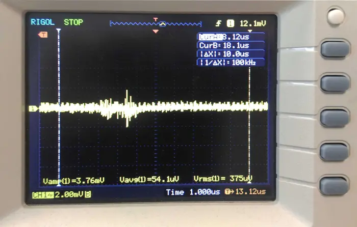
Some engineers make a distinction between output ripple and output noise. Both phenomena are an unwanted signal superimposed on the pure perfect dc output you want (Fig. 1). The source of ripple is the periodic input frequency, as well as the switching frequency of the control chip. An ac-dc supply will have a 50-, 60-, or perhaps 400-Hz input frequency. No matter how good the switching chip you use, a little of this frequency will bleed though the switching circuit.

1. In the most general sense, power-supply noise is the combination of unwanted periodic ripple and spikes combined with random noise from the devices or external sources. (Courtesy of Element14/Newark)

The amount of input-referred ripple will be governed by the line regulation of your design. This is a similar concept to power-supply rejection ratio (PSRR)—how much of the input signal a linear regulator lets pass to the output. It’s not solely a function of the control chip as much as the workings of the entire circuit.

A PSRR of 60 dB means any deviation at the input will be attenuated by 1000 at the output. A primary way to improve line regulation is to increase the gain of the control circuit. The higher the gain of the control loop, the smaller the error at the output; input ripple is just another error that must be dealt with by the loop. You can also use larger input capacitors, which will reduce the ripple on your dc input bus, so the PSRR of the control loop will apply to a smaller deviation.

On top of any inherent ripple in the output will be random noise generated by the control chip voltage reference and all other sources of thermal, shot, and flicker noise . There are three common ways to deal with this noise, that often help with ripple as well:

Filtering

You can use a filter to remove noise from a power supply just like you use filters to remove noise from a signal. Indeed, you can consider the output capacitors part of a filter that reacts against the output impedance of the power-supply circuit. Increasing the value of the output capacitance will reduce noise.

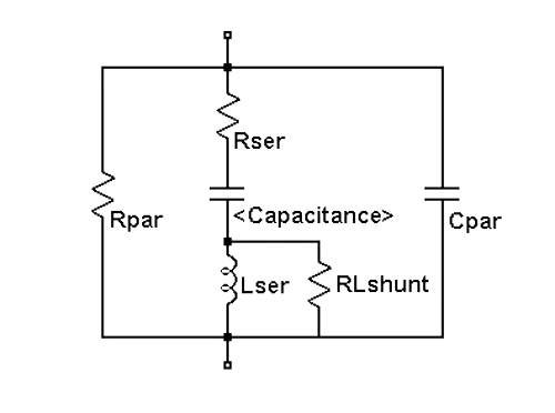
Be aware that capacitors have both an equivalent series resistance (ESR) and an equivalent series inductance (ESL) (Fig. 2). Selecting capacitors with lower ESR and ESL will lower noise, but be careful, some power-supply circuits use the ESR to provide the error signal for feedback. If you reduce it radically, say, by replacing electrolytic capacitors with ceramic ones, you may make your power supply unstable.

2. Capacitors have many stray elements, as is shown with this Spice equivalent circuit. The Lser and Rser in this schematic represent the equivalent series inductance (ESL) and equivalent series resistance (ESR). The Cpar, Rpar and RLshunt elements are usually negligible in most circuit applications. (Courtesy of LTWiki.org)

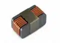
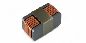
In addition to the natural output capacitance of the power supply, you might add a series inductor and another filter capacitor to further reduce output noise (Fig. 3). The inductor passes dc current with negligible loss, while providing a high-frequency impedance that the capacitor can react against to filter out the noise. In essence, you’re increasing the high-frequency output impedance of the supply so that you can more effectively filter it with smaller capacitors.

3. To lower the noise of a power rail to a load (R L), you can make an L-C low-pass filter. (Courtesy of Wikimedia)

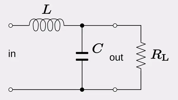
The problem with adding LC circuits is that they have a natural resonant frequency. Thus, it may make your supply unstable or produce unacceptable ringing after transient load changes. If the supply is providing low currents, you may be able to use a resistor instead of an inductor. That will create a dc loss term, but the resistor also adds damping to your output filter.

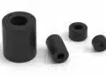
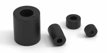
One filter useful for switching spikes and other high-frequency output noise are ferrite beads. The magnetic coupling with the output trace or wire and the bead will attenuate the noise. Another output noise source might be electromagnetic coupling from the outside world. Here you use shielding to protect the power-supply circuit from external influences.

Also note that your circuit board traces have inductance, and you might need to tailor that with power planes and trace widths. Using twisted-pair wiring is a good way to reduce inductance in order to prevent ringing and overshoot spikes. Adding any filter may increase the startup time and transient response of your system. If you’re cycling power to take a measurement and then shutting down, you have to trade off the filtering effectiveness with your startup time requirement.

Bypassing

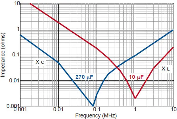
Perhaps less obvious, you can also reduce noise via proper bypassing of the control chips in your power-supply design. Bypassing the chips that being fed by the power supply will not reduce the noise at the supply, but it will be reduced at the power pins of the chips. When you bypass the chips in your power-supply circuit, use the normal guidelines of putting the capacitor close to the power pins and employ ceramic capacitors, preferably surface-mount, which have low ESR and ESL. Note that the capacitor’s physical size will dictate its effectiveness as much as its value (Fig. 4).

4. At low frequencies, the impedance of a 270-µF capacitor is lower than that of a 10-µF version, as you would expect. At 1 MHz, the 10-µF cap has a lower impedance due to self-resonance from stray inductance. You need to look at the impedance curves of various capacitor package sizes to ensure you’re getting the lowest impedance at the frequencies you’re trying to filter. (Courtesy of Johanson Dielectrics)

Post-regulation

A good, but expensive, way to reduce power-supply noise is to put a second low-noise regulator on the power-supply output. This often involves a low-dropout (LDO) linear regulator. It will reduce any output ripple by an order of magnitude or more. Better yet, you can add an RC or LC filter after the LDO to reduce noise even further. The noise of a linear regular is often expressed as an RMS value over one or more frequency ranges. If you need a very precise and low-drift power source, you can use a reference chip instead of an LDO regulator.

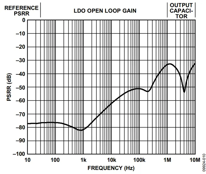
One thing to keep in mind is the frequency ranges that experience noise. Amplifiers also have power-supply rejection, and this rejection drops off significantly at high frequencies. Unfortunately, the PSRR of linear regulators also gets much worse at high frequencies (Fig. 5).

5. An LDO regulator has much better power-supply rejection ratio (PSRR) at low frequencies. The reference PSRR dominates at low frequencies, whereas the gain of the internal loop provides the PSRR at mid-range frequencies. At high frequencies, the output capacitors dominate PSRR, and the curve is similar to that shown in Figure 4. (Courtesy of Analog Devices)

However, such high-frequency noise is much easier to remove with LC or RC filtering, so all is not lost. The holistic approach is to remove noise at the input to the switcher, then bypass and make sure your switching IC chip is low noise. After that, pick a low-noise LDO linear regulator, so that you can then add an output filter. You should examine the PSRR of the chips you’re powering and intersect that with the PSRR of the linear regulator to remove as much noise as you can over the frequency bandwidth of your circuit. Then design the filter to remove sufficient high-frequency noise to achieve your signal-path noise goals.

Final Trick as a Bonus

Filtering, bypass, and post-regulation are the three primary ways to reduce power-supply noise, but there are some less-used techniques. One is to use a battery to power your circuitry. Batteries are a very low noise power source compared to switching or even linear converters. Another trick is available if you only need infrequent measurements. You can disable the switching regulator momentarily and use large hold-up capacitors to power your circuit while taking the measurement. A final trick is to synchronize the switch regulator with the acquisition of the measurement, so that it occurs at the same point in the ripple and other periodic noise of the supply. This is similar to synchronizing multiple switching power supplies. In that case, you’re trying to eliminate any beat frequency created by different switching frequencies.

Related

Source: ElectronicDesign

Recent Posts

Silicon Capacitors Market: Shaping the Foundation for Next-Gen Miniaturization Electronics

10.10.2025
6

YAGEO Releases Compact Coupled Inductors for High-Density VR Designs

9.10.2025
12

Enhancing Energy Density in Nanocomposite Dielectric Capacitors

9.10.2025
14

Advances in the Environmental Performance of Polymer Capacitors

8.10.2025
31

Vishay Releases DLA Tantalum Polymer Capacitors for Military and Aerospace

8.10.2025
15

Vishay Expanded Inductor Portfolio With More Than 2000 Stock Items 

8.10.2025
11

Paumanok Releases Capacitor Foils Market Report 2025-2030

7.10.2025
16

Modelithics Welcomes CapV as a Sponsoring MVP

7.10.2025
3

Benefits of Tantalum Powder Stress–Strain Curve Evaluation vs Conventional Wet Test

3.10.2025
23

Electrolyte Selection and Performance in Supercapacitors

3.10.2025
31

Upcoming Events

Oct 14
16:00 - 17:00 CEST

Smart Sensors, Smarter AI: Building Reliable Edge Systems

Oct 17
12:00 - 14:00 EDT

External Visual Inspection per MIL-STD-883 TM 2009

Oct 20
October 20 - October 23

Digital WE Days 2025 – Virtual Conference

Oct 21
October 21 @ 12:00 - October 23 @ 14:15 EDT

Space and Military Standards for Hybrids and RF Microwave Modules

Oct 28
8:00 - 15:00 CET

Power Up Your Design: SN6507 and the Ready-to-Use Development Kit

View Calendar

Popular Posts

  • Buck Converter Design and Calculation

    0 shares
    Share 0 Tweet 0
  • Boost Converter Design and Calculation

    0 shares
    Share 0 Tweet 0
  • Flyback Converter Design and Calculation

    0 shares
    Share 0 Tweet 0
  • LLC Resonant Converter Design and Calculation

    0 shares
    Share 0 Tweet 0
  • What is a Dielectric Constant and DF of Plastic Materials?

    4 shares
    Share 4 Tweet 0
  • SEPIC Converter Design and Calculation

    0 shares
    Share 0 Tweet 0
  • Dual Active Bridge (DAB) Topology Explained

    0 shares
    Share 0 Tweet 0
  • Ripple Current and its Effects on the Performance of Capacitors

    3 shares
    Share 3 Tweet 0
  • MLCC and Ceramic Capacitors

    0 shares
    Share 0 Tweet 0
  • Flying Capacitors Explained

    0 shares
    Share 0 Tweet 0

Newsletter Subscription


Passive Components Blog

© EPCI - Leading Passive Components Educational and Information Site

  • Home
  • Privacy Policy
  • EPCI Membership & Advertisement
  • About

No Result
View All Result
  • Home
  • Knowledge Blog
  • Premium Suppliers

© EPCI - Leading Passive Components Educational and Information Site

This website uses cookies. By continuing to use this website you are giving consent to cookies being used. Visit our Privacy and Cookie Policy.
Go to mobile version