Passive Components Blog
No Result
View All Result
  • Home
  • NewsFilter
    • All
    • Aerospace & Defence
    • Antenna
    • Applications
    • Automotive
    • Capacitors
    • Circuit Protection Devices
    • electro-mechanical news
    • Filters
    • Fuses
    • Inductors
    • Industrial
    • Integrated Passives
    • inter-connect news
    • Market & Supply Chain
    • Market Insights
    • Medical
    • Modelling and Simulation
    • New Materials & Supply
    • New Technologies
    • Non-linear Passives
    • Oscillators
    • Passive Sensors News
    • Resistors
    • RF & Microwave
    • Telecommunication
    • Weekly Digest

    3-Phase EMI Filter Design, Simulation, Calculation and Test

    YAGEO Unveils Compact 2.4 GHz SMD Antenna

    KYOCERA AVX Releases Antenna for Iridium Satellite IoT Applications

    Molex Releases Industry-First Quad-Row Board-to-Board Connectors with EMI Shields

    Image credit: Samtec

    How to Match the Right Connector with Protocol Requirements

    Smoltek CNF-MIM Capacitors Pass 1,000h Reliability Test

    Capacitor Lead Times: October 2025

    Paumanok Unveils Aluminum Capacitor Foils World Markets Study 2025-2030

    Coilcraft Introduces Ultra-Low Loss Shielded Power Inductors

    Trending Tags

    • Ripple Current
    • RF
    • Leakage Current
    • Tantalum vs Ceramic
    • Snubber
    • Low ESR
    • Feedthrough
    • Derating
    • Dielectric Constant
    • New Products
    • Market Reports
  • VideoFilter
    • All
    • Antenna videos
    • Capacitor videos
    • Circuit Protection Video
    • Filter videos
    • Fuse videos
    • Inductor videos
    • Inter-Connect Video
    • Non-linear passives videos
    • Oscillator videos
    • Passive sensors videos
    • Resistor videos

    3-Phase EMI Filter Design, Simulation, Calculation and Test

    Transformer Design Optimization for Power Electronics Applications

    Common Mode Chokes Selection for RF Circuits in Next-Generation Communication Systems

    Capacitor Self-balancing in a Flying-Capacitor Buck Converter

    How to Select Ferrite Bead for Filtering in Buck Boost Converter

    Power Inductors Future: Minimal Losses and Compact Designs

    Percolation Phenomenon: Degradation of Molded Power Inductors in DC/DC Converters

    Connector PCB Design Challenges

    Efficient Power Converters: Duty Cycle vs Conduction Losses

    Trending Tags

    • Capacitors explained
    • Inductors explained
    • Resistors explained
    • Filters explained
    • Application Video Guidelines
    • EMC
    • New Products
    • Ripple Current
    • Simulation
    • Tantalum vs Ceramic
  • Knowledge Blog
  • Suppliers
    • Who is Who
  • PCNS
    • PCNS 2025
    • PCNS 2023
    • PCNS 2021
    • PCNS 2019
    • PCNS 2017
  • Events
No Result
View All Result
Passive Components Blog
No Result
View All Result

How to Use NTC Thermistors for Inrush Current Limiting

1.10.2025
Reading Time: 5 mins read
A A

At the time of powering on an electronic device such as a switch-mode power supply (SMPS) or an inverter, the device is charged with an instantaneous abnormal current with a high peak. It is called an inrush current, and without protection, it may destroy a semiconductor device or have a harmful effect on the service life of a smoothing capacitor. NTC thermistors are used as ICLs (inrush current limiters) to protect circuits of electrical and electronic devices against inrush currents easily and effectively.

Advantages of NTC thermistors

RelatedPosts

Overvoltage Protection Selection Guidelines: TVS Diodes, MOVs, and ESD MOV Varistors

ESD Electrostatic Discharge Protection by TVS Diode

Chip Varistors Applications for ESD Countermeasures

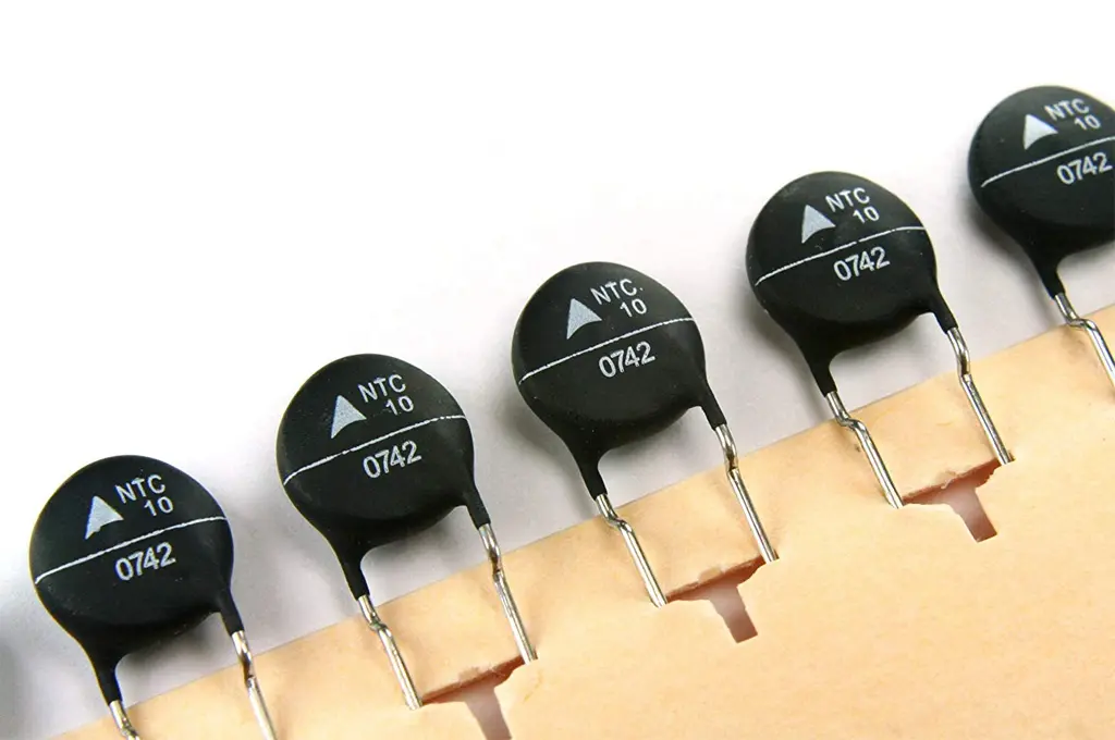
NTC thermistors are temperature-dependent resistors that employ special semiconductor ceramics with a negative temperature coefficient (NTC). They have a high resistance at room temperature, and when they are energized, they generate heat by themselves and the resistance falls as their temperature rises. With this property, they are used as current protection devices for electrical and electronic devices which easily and effectively limit abnormal currents including an inrush current at the time of powering on. 

NTC thermistors used as current protection devices are also called power thermistors.A fixed resistance or an NTC thermistor can be used to limit inrush currents.

However, a fixed resistor always causes a power loss and a decrease in performance. An NTC thermistor limits an inrush current with its high initial resistance, and then its temperature rises because of energization and its resistance falls to a few percent of its level at room temperature, thus achieving a power loss that is lower than when a fixed resistor is used. In other words, the effect of limiting inrush currents obtained by using an NTC thermistor is greater than that obtained by using a fixed resistor with comparable initial power losses.

The following are details of sample applications of NTC thermistors for inrush current limiting.

Application: Inrush current limiting in a switching power supply

Various switch-mode power supplies (SMPS) – which are small, lightweight, and high-performance – are often used as power supplies of electronic devices. At the time of powering on an SMPS, the device is charged with an inrush current with a high peak to charge a smoothing capacitor. Because this inrush current may negatively impact the service life of the capacitor, damage the contacts of the power switch, or destroy a rectifier diode, it is necessary to take countermeasures. As shown in the figure below, limiting the inrush current of an SMPS by inserting an NTC thermistor is widely used as a way of making a low-cost and easy circuit for limiting inrush currents in power supplies. The same result can be achieved even when the NTC thermistor is connected after the rectifier circuit.

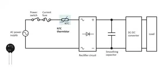
Figure 1 Inrush current limiting in a switch-mode power supply

Application: Inrush current limiting in an AC-DC power module

A built-in power supply with various power circuits and peripheral circuits compactly integrated is called a power module. An AC-DC power module is a power supply constructed by combining an AC-DC rectifier circuit and a DC-DC converter, and with a small quantity of external parts, it can realize a space-saving optimized power supply system. An inrush current applied to input and output capacitors at the time of powering on can be effectively limited by inserting an NTC thermistor (power thermistor).

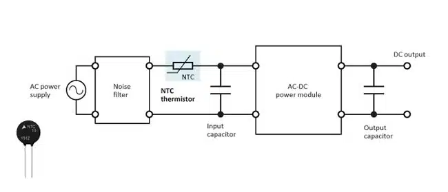
Figure 2 Inrush current limiting in an AC-DC power module

Application: Inrush current limiting in a DC-DC converter

In the DC power circuit of a DC-DC converter or the like, an NTC thermistor is used as a power thermistor and effectively limits an inrush current, with which the input and output capacitors are charged at the time of powering on. The resistance of the NTC thermistor becomes very low after it is energized, which achieves a power loss that is lower than when a fixed resistance is used.

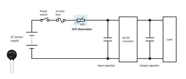
Figure 3 Inrush current limiting in a DC-DC converter

Application: Inrush current limiting in an industrial inverter

Induction motors are often used for fans, pumps, air conditioners, and others in factories, large facilities, office buildings, and the likes. An induction motor is simple in structure and stable, however, its rotation speed is dependent on the frequency. Inverters are needed in order to control the rotation speed. Motors equipped with inverters are known as variable speed drives (VSD), which are able to significantly reduce power consumption.
An inverter system consists of a converter part, an inverter part, and a DC link capacitor (smoothing capacitor) that is placed after the converter part. At the time of powering on, the device is charged with an inrush current of which whose peak is several times as large as larger than that of steady current to charge the DC link capacitor. This inrush current may have a harmful effect on the service life of a DC capacitor or destroy a semiconductor device. To protect against the inrush current, NTC thermistors (power thermistors) are connected.

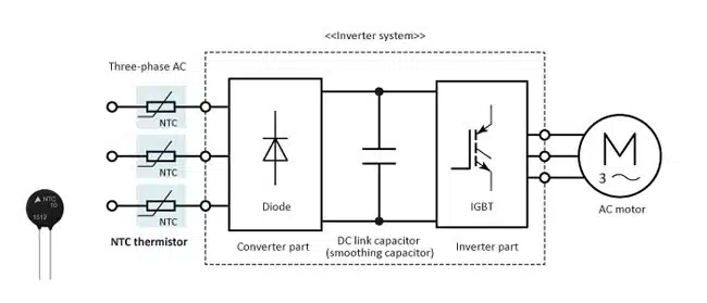
Figure 4 Inrush current limiting in an industrial inverter (three-phase)

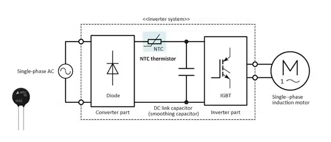
Figure 5 Inrush current limiting in an industrial inverter (single-phase)

Related

Source: TDK

Recent Posts

3-Phase EMI Filter Design, Simulation, Calculation and Test

6.11.2025
4

Molex Releases Industry-First Quad-Row Board-to-Board Connectors with EMI Shields

6.11.2025
2
Image credit: Samtec

How to Match the Right Connector with Protocol Requirements

6.11.2025
2

Capacitor Lead Times: October 2025

6.11.2025
6

Coilcraft Introduces Ultra-Low Loss Shielded Power Inductors

6.11.2025
2

Würth Elektronik Expands its MagI³C-VDMM MicroModules

5.11.2025
7

Littelfuse Releases Load-Powered Compact Relay

5.11.2025
10

Transformer Design Optimization for Power Electronics Applications

4.11.2025
11

Microhardness — the Hidden Key to Understanding MnOx Cathode Quality in Tantalum Capacitors

3.11.2025
17

Lightweight Model for MLCC Appearance Defect Detection

3.11.2025
20

Upcoming Events

Nov 11
17:00 - 18:00 CET

Industrial Applications Demand More from Interconnects in Next-Gen Designs

Nov 12
11:00 - 12:00 CET

PCB Design: Impedance is for everyone!

Nov 12
November 12 @ 12:00 - November 13 @ 14:15 EST

Microelectronic Packaging Failure Modes and Analysis

View Calendar

Popular Posts

  • Buck Converter Design and Calculation

    0 shares
    Share 0 Tweet 0
  • Boost Converter Design and Calculation

    0 shares
    Share 0 Tweet 0
  • LLC Resonant Converter Design and Calculation

    0 shares
    Share 0 Tweet 0
  • Flyback Converter Design and Calculation

    0 shares
    Share 0 Tweet 0
  • Ripple Current and its Effects on the Performance of Capacitors

    3 shares
    Share 3 Tweet 0
  • MLCC and Ceramic Capacitors

    0 shares
    Share 0 Tweet 0
  • Dual Active Bridge (DAB) Topology

    0 shares
    Share 0 Tweet 0
  • What is a Dielectric Constant and DF of Plastic Materials?

    4 shares
    Share 4 Tweet 0
  • SEPIC Converter Design and Calculation

    0 shares
    Share 0 Tweet 0
  • Flying Capacitors

    0 shares
    Share 0 Tweet 0

Newsletter Subscription


Passive Components Blog

© EPCI - Leading Passive Components Educational and Information Site

  • Home
  • Privacy Policy
  • EPCI Membership & Advertisement
  • About

No Result
View All Result
  • Home
  • Knowledge Blog
  • PCNS

© EPCI - Leading Passive Components Educational and Information Site

This website uses cookies. By continuing to use this website you are giving consent to cookies being used. Visit our Privacy and Cookie Policy.
Go to mobile version