Passive Components Blog
No Result
View All Result
  • Home
  • NewsFilter
    • All
    • Aerospace & Defence
    • Antenna
    • Applications
    • Automotive
    • Capacitors
    • Circuit Protection Devices
    • electro-mechanical news
    • Filters
    • Fuses
    • Inductors
    • Industrial
    • Integrated Passives
    • inter-connect news
    • Market & Supply Chain
    • Market Insights
    • Medical
    • Modelling and Simulation
    • New Materials & Supply
    • New Technologies
    • Non-linear Passives
    • Oscillators
    • Passive Sensors News
    • Resistors
    • RF & Microwave
    • Telecommunication
    • Weekly Digest

    Modelithics Releases COMPLETE Library v25.6 for Keysight ADS with 14 New Scalable Models

    Knowles Releases High Q Non-Magnetic X7R MLCCs for Medical Imaging

    Researchers Developed Reduced Graphene Oxide (rGO) High Energy Density Graphene Supercapacitors

    Samtec Agreed with Molex Second-Source License on High-Speed Interconnects for Data Centers

    Panasonic Industry Releases Highest Capacitance 63V Conductive Polymer Tantalum Capacitors in 3mm Height

    August 2025 ECIA US Components Sales Sentiment Remains Strong

    Vishay Releases Industry First Automotive SMD Y1 Safety Ceramic Capacitors

    Researchers Enhanced 2D Ferromagnets Performance

    Bourns Releases Two High Current Common Mode Choke Models

    Trending Tags

    • Ripple Current
    • RF
    • Leakage Current
    • Tantalum vs Ceramic
    • Snubber
    • Low ESR
    • Feedthrough
    • Derating
    • Dielectric Constant
    • New Products
    • Market Reports
  • VideoFilter
    • All
    • Antenna videos
    • Capacitor videos
    • Circuit Protection Video
    • Filter videos
    • Fuse videos
    • Inductor videos
    • Inter-Connect Video
    • Non-linear passives videos
    • Oscillator videos
    • Passive sensors videos
    • Resistor videos

    Ripple Steering in Coupled Inductors: SEPIC Case

    SEPIC Converter with Coupled and Uncoupled Inductors

    Coupled Inductors in SEPIC versus Flyback Converters

    Non-Linear MLCC Class II Capacitor Measurements Challenges

    Percolation Phenomenon and Reliability of Molded Power Inductors in DC/DC converters

    Root Causes and Effects of DC Bias and AC in Ceramic Capacitors

    How to Calculate the Output Capacitor for a Switching Power Supply

    Switched Capacitor Converter Explained

    Understanding Inductor Dot Markings and Their Application in LTspice

    Trending Tags

    • Capacitors explained
    • Inductors explained
    • Resistors explained
    • Filters explained
    • Application Video Guidelines
    • EMC
    • New Products
    • Ripple Current
    • Simulation
    • Tantalum vs Ceramic
  • Knowledge Blog
  • Suppliers
    • Who is Who
  • Events
No Result
View All Result
Passive Components Blog
No Result
View All Result

Microwave Multi Line Connectors Mounting and Handling Precautions

11.8.2025
Reading Time: 2 mins read
A A

This video from Murata covers handling precautions to ensure that microwave multi line connectors are used properly. Refer to this information to prevent failures.

Best Practices for Using Microwave Multi-Line Connectors

RelatedPosts

High Voltage MLCCs Meeting the Growing Demand for Efficiency in Power Conversion

Murata Releases In-vehicle Compact Crystal in 2016 Size

Murata Announces Mass Manufacturing of World’s First 0402 47µF MLCC

Introduction

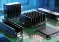
Microwave multi-line connectors are critical components in high-frequency applications, requiring precise handling and mounting procedures to ensure optimal performance. This article outlines essential precautions related to solder paste application, mounting, and mating to prevent common issues such as solder wicking, cracks, and operational failures.

Solder Paste Application Precautions

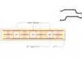
The amount of solder paste applied to microwave multi-line connectors is crucial. If the size of the land pattern matches the stencil mask opening, the solder paste amount may be excessive, leading to solder wicking. Solder wicking can result in solder or flux infiltrating the connector, adversely affecting mating and RF measurement performance. In severe cases, it may cause short circuits between terminals. Conversely, insufficient solder paste can lead to inadequate solder strength, potentially causing open circuits.

To mitigate these issues, ensure the stencil mask opening is smaller than the land pattern. Verify the stencil mask thickness and dimensions against the specifications for both foreign and stencil mask patterns.

Mounting Precautions

The standard mounting procedure involves using a suction nozzle to transfer a connector from carrier tape to the board. Cracks, which can compromise connector quality, may occur due to external forces during mounting. These cracks often result from excessive load when the suction nozzle’s bottom dead center is too low.

To prevent cracks, avoid applying loads beyond the bottom dead center. Verify the height of each connector and input the bottom dead center information into the component library within the mounter. Additionally, inspect for foreign substances between the board and connector, as these can also cause excessive load and cracks. Ensure the nozzle size is appropriate and that it grips connectors at the plastic part. Weld lines do not affect connector performance and can be used as is.

Mating Precautions

Improper mating, such as slanting or misalignment, can lead to operational failures or connector damage. To ensure proper mating, do not apply force until alignment is achieved. Push vertically and apply force until a click is felt, then stop to prevent connector deformation.

Conclusion

To utilize microwave multi-line connectors effectively, adhere to the following guidelines: apply the correct amount of solder paste, mount connectors according to prescribed procedures, and use the proper mating technique. By following these best practices, you can enhance the reliability and performance of your microwave multi-line connectors.

Related

Source: Murata

Recent Posts

Panasonic Industry to Double Production of MEGTRON PCB Materials

15.9.2025
8

Glass Core Technology Breakthrough Potential for High-Speed Interconnects

12.6.2025
50

What Track Width To Use When Routing PCB

6.6.2025
61

Highly Reliable Flex Rigid PCBs, Würth Elektronik Webinar

15.5.2025
49

High-Density PCB Assemblies For Space Applications

2.5.2025
52

IPC Class 2 vs Class 3 Solder Joints Requirements Explained

27.2.2025
516

HIROSE Expands Open Pluggable OPS PCB connector

9.1.2025
52

How to Determine Chip Temperature

3.1.2025
220

Die and Wire PCB Bonding Explained

1.7.2025
159

Polymer Materials and Processing

11.8.2025
52

Upcoming Events

Sep 22
September 22 @ 13:00 - September 25 @ 15:15 EDT

Pre Cap Visual Inspection per Mil-Std-883 (TM 2017)

Sep 30
September 30 @ 12:00 - October 2 @ 14:00 EDT

MIL-Std-883 TM 2010

Oct 17
12:00 - 14:00 EDT

External Visual Inspection per MIL-STD-883 TM 2009

Oct 20
October 20 - October 23

Digital WE Days 2025 – Virtual Conference

Oct 21
October 21 @ 12:00 - October 23 @ 14:15 EDT

Space and Military Standards for Hybrids and RF Microwave Modules

View Calendar

Popular Posts

  • Buck Converter Design and Calculation

    0 shares
    Share 0 Tweet 0
  • Boost Converter Design and Calculation

    0 shares
    Share 0 Tweet 0
  • Flyback Converter Design and Calculation

    0 shares
    Share 0 Tweet 0
  • LLC Resonant Converter Design and Calculation

    0 shares
    Share 0 Tweet 0
  • Dual Active Bridge (DAB) Topology Explained

    0 shares
    Share 0 Tweet 0
  • Ripple Current and its Effects on the Performance of Capacitors

    3 shares
    Share 3 Tweet 0
  • What is a Dielectric Constant and DF of Plastic Materials?

    4 shares
    Share 4 Tweet 0
  • SEPIC Converter Design and Calculation

    0 shares
    Share 0 Tweet 0
  • How to Design an Inductor

    0 shares
    Share 0 Tweet 0
  • Core Materials, Permeability and Their Losses

    0 shares
    Share 0 Tweet 0

Newsletter Subscription


Passive Components Blog

© EPCI - Leading Passive Components Educational and Information Site

  • Home
  • Privacy Policy
  • EPCI Membership & Advertisement
  • About

No Result
View All Result
  • Home
  • Knowledge Blog
  • Premium Suppliers

© EPCI - Leading Passive Components Educational and Information Site

This website uses cookies. By continuing to use this website you are giving consent to cookies being used. Visit our Privacy and Cookie Policy.
Go to mobile version