Passive Components Blog
No Result
View All Result
  • Home
  • NewsFilter
    • All
    • Aerospace & Defence
    • Antenna
    • Applications
    • Automotive
    • Capacitors
    • Circuit Protection Devices
    • electro-mechanical news
    • Filters
    • Fuses
    • Inductors
    • Industrial
    • Integrated Passives
    • inter-connect news
    • Market & Supply Chain
    • Market Insights
    • Medical
    • Modelling and Simulation
    • New Materials & Supply
    • New Technologies
    • Non-linear Passives
    • Oscillators
    • Passive Sensors News
    • Resistors
    • RF & Microwave
    • Telecommunication
    • Weekly Digest

    Transformer Safety IEC 61558 Standard

    ESR of Capacitors, Measurements and Applications

    Murata Christophe Pottier Appointed President of EPCIA

    3-Phase EMI Filter Design, Simulation, Calculation and Test

    YAGEO Unveils Compact 2.4 GHz SMD Antenna

    KYOCERA AVX Releases Antenna for Iridium Satellite IoT Applications

    Molex Releases Industry-First Quad-Row Board-to-Board Connectors with EMI Shields

    Image credit: Samtec

    How to Match the Right Connector with Protocol Requirements

    Smoltek CNF-MIM Capacitors Pass 1,000h Reliability Test

    Trending Tags

    • Ripple Current
    • RF
    • Leakage Current
    • Tantalum vs Ceramic
    • Snubber
    • Low ESR
    • Feedthrough
    • Derating
    • Dielectric Constant
    • New Products
    • Market Reports
  • VideoFilter
    • All
    • Antenna videos
    • Capacitor videos
    • Circuit Protection Video
    • Filter videos
    • Fuse videos
    • Inductor videos
    • Inter-Connect Video
    • Non-linear passives videos
    • Oscillator videos
    • Passive sensors videos
    • Resistor videos

    Transformer Safety IEC 61558 Standard

    3-Phase EMI Filter Design, Simulation, Calculation and Test

    Transformer Design Optimization for Power Electronics Applications

    Common Mode Chokes Selection for RF Circuits in Next-Generation Communication Systems

    Capacitor Self-balancing in a Flying-Capacitor Buck Converter

    How to Select Ferrite Bead for Filtering in Buck Boost Converter

    Power Inductors Future: Minimal Losses and Compact Designs

    Percolation Phenomenon: Degradation of Molded Power Inductors in DC/DC Converters

    Connector PCB Design Challenges

    Trending Tags

    • Capacitors explained
    • Inductors explained
    • Resistors explained
    • Filters explained
    • Application Video Guidelines
    • EMC
    • New Products
    • Ripple Current
    • Simulation
    • Tantalum vs Ceramic
  • Knowledge Blog
  • Suppliers
    • Who is Who
  • PCNS
    • PCNS 2025
    • PCNS 2023
    • PCNS 2021
    • PCNS 2019
    • PCNS 2017
  • Events
No Result
View All Result
Passive Components Blog
No Result
View All Result

Negative Capacitor Enable Higher Voltage Systems

3.10.2022
Reading Time: 4 mins read
A A

by DOE/Argonne National Laboratory, original written by Jared Sagoff. Researchers have created a permanent static ‘negative capacitor,’ a device believed to have been in violation of physical laws until about a decade ago. Newly devised static negative capacitor could improve computing and yield more energy-efficient computers.

With a little physics ingenuity, scientists have designed a way to redistribute electricity on a small scale, potentially opening new avenues of research into more energy-efficient computing.

RelatedPosts

Transformer Safety IEC 61558 Standard

ESR of Capacitors, Measurements and Applications

Murata Christophe Pottier Appointed President of EPCIA

In a new study, researchers at the U.S. Department of Energy’s (DOE) Argonne National Laboratory, together with collaborators in France and Russia, have created a permanent static “negative capacitor,” a device thought to have been in violation of physical laws until about a decade ago.

“The objective is to be able to get electricity where it is needed while using as little as possible in a controlled static regime.” — Argonne materials scientist Valerii Vinokur

While previously proposed designs for negative capacitors worked on a temporary, transient basis, the new Argonne-developed negative capacitor concept works as a steady-state, reversible device.

The researchers found that by pairing a negative capacitor in series with a positive capacitor, they could locally increase the voltage on the positive capacitor to a point higher than the total system voltage. In this way, they could distribute electricity to regions of a circuit requiring higher voltage while operating the entire circuit at lower voltage.

“The objective is to get electricity where it is needed while using as little as possible in a controlled, static regime,” said Argonne materials scientist Valerii Vinokur, the corresponding author of the study.

In traditional capacitors, the electric voltage of the capacitor is proportional to their stored electrical charge — increasing the amount of stored charge increases the voltage. In negative capacitors, the opposite happens — increasing the amount of charge decreases the voltage. Because the negative capacitor is a part of the larger circuit, this does not violate conservation of energy.

“One way you can think about it is like having a refrigerator,” said University of Picardie (France) scientist Igor Lukyanchuk, the first author of the paper. “Inside the refrigerator, of course, it is much colder than the outside environment, but that is because we are heating up the rest of the environment by expending energy to cool the refrigerator.”

A prime component of the negative capacitor put forward by Vinokur and his colleagues involves a filling made of a ferroelectric material, which is similar to a magnet except that it has an internal electric polarization, rather than a magnetic orientation.

“In a ferroelectric nanoparticle, on one surface you will have a positive charge, and at the other surface you will have negative charges,” Vinokur said. “This creates electric fields that try to depolarize the material.”

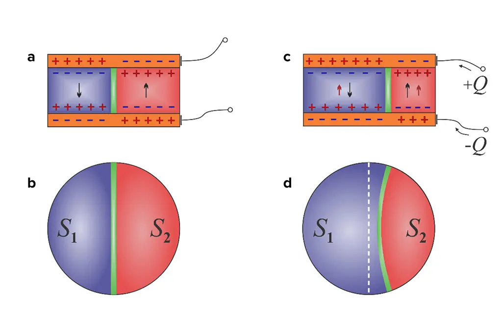
By splitting a nanoparticle into two equal ferroelectric domains of opposite polarization, separated by a boundary called a domain wall, Vinokur and his colleagues were able to minimize the effect of the total depolarizing electric field. Then, by adding charge to one of the ferroelectric domains, the researchers shifted the position of the domain wall between them.

Because of the cylindrical nature of the nanoparticle, the domain wall began to shrink, causing it to displace beyond the new electric equilibrium point. “Essentially, you can think of the domain wall like a fully extended spring,” said Lukyanchuk. “When the domain wall displaces to one side because of the charge imbalance, the spring relaxes, and the released elastic energy propels it further than expected. This effect creates the static negative capacitance.”

An article based on the study, “Harnessing ferroelectric domains for negative capacitance,” appeared in the February 26 online edition of Communications Physics. Authors of the study also include Anaïs Sené of the University of Picardie, and Yuri Tikhonov and Anna Razumnaya of the Southern Federal University (Russia).

The research at Argonne was funded by the DOE’s Office of Science. Research at the collaborating institutions was funded by the European Commission’s HORIZON 2020 initiative.

Journal Reference:

I. Luk’yanchuk, Y. Tikhonov, A. Sené, A. Razumnaya, V. M. Vinokur. Harnessing ferroelectric domains for negative capacitance. Communications Physics, 2019; 2 (1) DOI: 10.1038/s42005-019-0121-0

featured image: shows the movement of the domain wall (a-c and b-d) in a capacitor when a charge is added to one side (c). The resulting redistribution of the domain wall causes a negative capacitive effect. Credit: Argonne National Laboratory

Related

Source: Science Daily News

Recent Posts

Transformer Safety IEC 61558 Standard

7.11.2025
1

ESR of Capacitors, Measurements and Applications

7.11.2025
16

3-Phase EMI Filter Design, Simulation, Calculation and Test

6.11.2025
25

Molex Releases Industry-First Quad-Row Board-to-Board Connectors with EMI Shields

6.11.2025
8
Image credit: Samtec

How to Match the Right Connector with Protocol Requirements

6.11.2025
12

Smoltek CNF-MIM Capacitors Pass 1,000h Reliability Test

6.11.2025
9

Capacitor Lead Times: October 2025

6.11.2025
52

Paumanok Unveils Aluminum Capacitor Foils World Markets Study 2025-2030

6.11.2025
13

Coilcraft Introduces Ultra-Low Loss Shielded Power Inductors

6.11.2025
13

Würth Elektronik Expands its MagI³C-VDMM MicroModules

5.11.2025
9

Upcoming Events

Nov 11
17:00 - 18:00 CET

Industrial Applications Demand More from Interconnects in Next-Gen Designs

Nov 12
11:00 - 12:00 CET

PCB Design: Impedance is for everyone!

Nov 12
November 12 @ 12:00 - November 13 @ 14:15 EST

Microelectronic Packaging Failure Modes and Analysis

View Calendar

Popular Posts

  • Buck Converter Design and Calculation

    0 shares
    Share 0 Tweet 0
  • Boost Converter Design and Calculation

    0 shares
    Share 0 Tweet 0
  • LLC Resonant Converter Design and Calculation

    0 shares
    Share 0 Tweet 0
  • Flyback Converter Design and Calculation

    0 shares
    Share 0 Tweet 0
  • Ripple Current and its Effects on the Performance of Capacitors

    3 shares
    Share 3 Tweet 0
  • MLCC and Ceramic Capacitors

    0 shares
    Share 0 Tweet 0
  • Dual Active Bridge (DAB) Topology

    0 shares
    Share 0 Tweet 0
  • SEPIC Converter Design and Calculation

    0 shares
    Share 0 Tweet 0
  • What is a Dielectric Constant and DF of Plastic Materials?

    4 shares
    Share 4 Tweet 0
  • Flying Capacitors

    0 shares
    Share 0 Tweet 0

Newsletter Subscription


Passive Components Blog

© EPCI - Leading Passive Components Educational and Information Site

  • Home
  • Privacy Policy
  • EPCI Membership & Advertisement
  • About

No Result
View All Result
  • Home
  • Knowledge Blog
  • PCNS

© EPCI - Leading Passive Components Educational and Information Site

This website uses cookies. By continuing to use this website you are giving consent to cookies being used. Visit our Privacy and Cookie Policy.
Go to mobile version