


Tantalum capacitors are widely used in modern electronic devices due to their volumetric capacitive efficiency and reliability. The aim of the work published by Vladimir Azbel on his LinkedIn blog is to discuss some basic physical considerations of tantalum capacitor anode design to improve its capabilities towards further increase of volumetric efficiency and reliability.
The proposed new tantalum anode design approach increases the capacitor reliability and stability, as well as reduces the costs and time for the manufacture of the anode, on which the quality of the capacitor depends. Failure of the anode can lead to thermal destruction or explosion of the capacitor and, as a result, to the failure of products, which is especially critical in military, aerospace, and medical technology.
Improving the reliability of the anode can be achieved by
- optimizing the anode parameter at the design stage, for the required capacitor rating
- estimate of the stability (reliability) of leakage currents (DCL) by mechanical test /2 /
The reliability test is like a “bridge” that accelerates internal processes and evaluates their impact on product stability over time. A mechanical test was selected for the sintered pellet and anode using a stress-strain curve. The use of the parameters, stress-strain curve, allows, through direct measurements, to obtain quantitative estimates of the defectiveness of the sintered tablet and anode, which makes it possible to predict the process of their aging and, accordingly, to stabilize their properties during operation. This allows you to make changes to the manufacturing process.
without waiting for the end of the electrical tests. This approach allows not only to increase the reliability and stability of the anode but also to reduce the costs and time for its manufacture. This approach can be used not only when developing new products, but also to improve the reliability and stability of existing ones.
The “heart “of the Ta capacitor, responsible for its electrical characteristics, is the anode. The anode is porous powder metallurgy. Its electrical characteristics, such as capacitance and leakage currents (DCL), determined after the formation of sintered pellets and to depend on the morphology porous its structure and determined by way Wet test.
The morphology porous structure of the sintered pellet, which to set its the porosity(capacitance) and size of the necks (maximum acceptable formation voltage) is determined by CV/g of the powder, pressing density, sintering temperature/time and can be controlled by the characteristics obtained from the stress-strain curve
DCL of tantalum capacitors, in opposite to capacitance, tend to degrade during operation. This effect may be explained by aging processes in the anode caused by residual stresses. One of the stresses reasons may be the defects, which formed in the anode. Unfortunately, the structure of the sintered pellet cannot resist the influence of the formation process. The critical place of defects generation and accumulation is the neck of the sintered pellet. To produce a specific rating capacitor, it is important to achieve an optimal balance between the CV / g of the anode, the neck size of the sintered pellet, and the defectiveness of the anode.
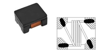
We presented a model of porous material as a cell consisting of four spherical particles (see fig. 1 a), allowing the formation of a pore and a neck (see figure 1b).
It is accepted that spherical particles are the primary powder particles with the asymmetric distribution.

The neck is the area between two adjacent primary powder particles radius Rp A and B (see Fig. 2a). In the proposed model, the neck is viewed as a cylindrical figure (see 2b). This is the region with the smallest cross-sectional area in the sintered porous material.

An increase in compacting density, sintering temperature/time leads to a decrease in porosity (It causes a decrease in capacity) and, accordingly, an increase in the neck of the sintered tablet. Received the anode, the sintered pellet is subjected to a formation process.
The formation process leads to the formation of amorphous tantalum oxide on the surface of the sintered pellet when passing a current through the electrolyte and the neck of the sintered pellet. An increase formation voltage leads to the growth of amorphous tantalum oxide inside (r1) and outside (r2), relative to the radius of the tantalum core neck (Rn).
An increase formation voltage (see Figure 4) leads to a decrease in the cross-sectional area of the tantalum core neck a sintered pellet (see Figure 3 a, b), and the pore size. An integral part of the formation process is the creation of a transition layer zone (red circles) between Ta and amorphous tantalum oxide. These materials have different coefficients of volumetric expansion, that causes, in the transition layer zone, the appearance of residual stresses. Their maximum is mainly concentrated in the neck area. The rate of aging and, accordingly, the stability of the leakage current during the exploitation of the capacitor depends on their value. The relaxation of residual stresses is achieved by heat treatment of the anode.
.

If the formation voltage is too high, the amorphous tantalum oxide overlaps the neck (Rn = r1 (see Fig. 4), the capacitance drops, and the risk of DCL failure increases.

The quality of amorphous tantalum oxide depends on the defectiveness of the anode, which in turn, depends on the technological process of anode production.
A decrease in the cross-sectional area of the tantalum core neck, with an increase in the formation voltage, causes an increase in the resistance to the flow of the formation current, which leads to an increase in the released energy (Wa) in the volume of the neck. The energy released in the conductor during the passage of an electric current is given by the equation Wa = Ir2 * ρ * h / S
where Wa according to the suggested model, this is the energy released in the volume of the neck, when an electric current passes through it, Ir is the formation current, ρ is the electrical resistivity Ta, h is the length of the neck, S is the cross-sectional area of the neck S = π * L2 / 4. where the value L = Rn on fig.4. decreases with the formation voltage.
The imbalance of heat exchange processes, when the heat transfer energy (Q) from the neck, becomes comparable to the emitted energy (Wa) in the neck region, increases the risk of overheating and leads to the transformation of amorphous tantalum oxide into crystalline one.
As the main mechanisms of heat transfer in the neck region, the transfer through the neck cross-sectional area (q) to the particle and the amorphous film (Q), around of a neck to the electrolyte is considered, the following expressions were used:
• q = k * S * ΔT / h, where q – heat energy transferred, S – cross-sectional area of a neck Ta, k – thermal conductivity of tantalum -0.4 (W m‑1 K‑1), ΔT-temperature change to ТС = 450 ° C which corresponds to the onset of crystallization of the amorphous film, his the neck length.
• Q = k1 * A * ΔT / d, where Q – heat energy transfer, A – surface area amorphous film, around of a neck Ta, k1 – thermal conductivity of amorphous film -0.7 (W m‑1 K‑1),, ΔT-temperature change to ТС = X ° C, which corresponds to the initial boiling point of the electrolyte, d- thickness of tantalum amorphous oxide film.
In addition to the influence of the formation current, the contribution of the generated heat (G) must be taken into account by the formation of tantalum oxide. The oxidation of tantalum is highly exothermic, thus the act of introducing air to the surface leads to the release of chemical energy. (H298K = -489 kcal / mole Ta2O5). Calculating the weight of the formed amorphous tantalum oxide film in the neck region (see Fig. 4) using the model, we can estimate G.
The heat (H) required to heat the neck mass to ТС = 450°C H = m * Cp * ΔT – heat needed to change the temperature (Cp -specific heat, the m-mass volume of the neck, ΔT-temperature change to ТС = 450°C which corresponds to the beginning of crystallization of the amorphous film)
In this work, we explain the degradation of the dielectric due to the processes occurring during the formation of the anode.
The reduction of the influence of these processes depends on the combination of the parameters determined by the developer (see table 1, green squares) and depends on risk of overheating. As a criterion for the risk of overheating, the value of the ratio Q / Wa
To reduce costs and decrease the development time of the anode, at the design stage, a model was built, and a criterion was proposed, that allows predicting the risk of anode overheating during formation. It is logical to assume that the critical place responsible for overheating during the passage of an electric current is the area with the smallest cross-sectional area of the material, which in the porous material is the neck of the sintered pellet and which decreases with increasing formation voltage.
The model makes it possible to establish a relationship between the parameters determined by the developer: tablet size (a, b, c), weight (), pressing density (P, g / cc), sintering temperature/time (T ° K / t, min.), Capacity (C), formation voltage (FV, V) and formation current (Ir, A), with the size of the neck of the sintered pellet (L, µ) and the value of the ratio Q/Wa, chosen as the criterion for overheating.
The proposed equation, in the form of an excel formula, allows you to calculate the anode for the parameters specified by the developer (see table 1).
In further calculations, the contribution of the energies G and H can be neglected in comparison with the heat energy transfer(Q)
Let us consider the influence of the formation current (Ir) on the value of the ratio Q/Wa, for the anodes presented in table 1 ratings. An increase Ir from variant 1 to 3, as seen from table 1, leads to a decrease in Q/Wa, independent of the CV/g of the powder used.
The calculated dimensions of the necks (see table 1, parameter L), for sintered pellet from powders of different CV/g (see table 1), is in the range of measurement errors, values determined by electron microscopy /3/. As shown /3/ that with increasing CV / g of powder, the neck size decreases, and inverse.
The Ir value in variant 1 (see Table 1), for the anodes of the ratings under consideration, corresponds to the value used in the production of capacitors based on them.
Invariant 2 (see table 1), the calculated value of Icalc is taken as Ir. When calculating the Icalc value. the heat energy transfer Q was used. It turned out, that the ratio Ir corresponding to variant1 (see table 1), for all ratings given in table 1, is within ~ 45-55% of their calculated value Icalc. (see table 1).
From table 1 shows, that a decrease in the formation current, leads to an increase in the value of the ratio Q / Wa. For the criterion of the ratio Q / Wa, the value corresponding to variant 1 (see table 1) was taken for which acceptable capacitors were obtained. The numerical values of Q / Wa correspond to more than 10. This criterion seems reasonable if we take into account that the calculations given in Table 1 for the expression of Wa do not take into account the effect of defects formed during the formation process on the resistance to current flow.
Therefore, the more the Q / Wa ratio is more than 10, the less the risk of overheating.

Using one rating as an example (see Table 2), we will demonstrate how changing one of the parameters given by the developer, affects the value of the ratio Q / Wa.
Increasing the compaction density (see table 2 variant 1a, 2a, and 3a), temperature (see tab.2var.2s), sintering time (see tab.2var.3c), and lowering the formation voltage (see tab.2var.2b) leads to an increase in the size of the neck of the sintered tablet (L) and, accordingly, the ratio Q / Wa

An increase in the value of the ratio Q / Wa can be achieved
- In a sintered pellet, the neck size to increase, by way of increasing the press density, sintering temperature/time, or decreasing the CV/g of the powder used.
- In the anode by reducing the current and voltage of formation
The model allows calculating the neck size and formation current and their effect on the Q / Wa ratio. Such calculating reduces, the number of experiments to obtain an acceptable result.
After the production of the anode, according to the calculation performed, in order to estimate the risk of its acceptability for production, besides values to the capacity and leakage currents, it is necessary to check their stability, during the exploitation of the capacitor, which depends on aging processes. The latter depends on the defectiveness accumulated anode in the process manufactory
1. To estimate the defectiveness of the sintered pellet and the anode, it is proposed to use the method of loading the test samples by compression, specially adapted for these purposes, with the recording of the CC curve, which made it possible to formulate criteria for their acceptability
a) for a sintered pellet, it is necessary to provide a combination between the required capacity value, determined from the wet test, with the values of plastic deformation, which should not be less than 10%, and an exponential index, not more than 0.5, determined from the CC curve./1/
b) for the anode, this is determined by the ratio, the yield stress of the anode before (Ϭa) and after aging at 450 ° C / 20 min. (Ϭagn) to Ϭa, which should not exceed 10-15%. /2/
References
- Method for determining the reliability of a tantalum capacitor (part 1- sintering) linkedin.com/in/vladimir-azbel-319769106 Azbel V.
- Mechanical stress of anodized pellet predicts the Ta-capacitor reliability https://passive-components.eu/method-for-determining-the-reliability-of-a-tantalum-capacitor-part-1/ Azbel V.
- Magnesium Vapour Reduced Tantalum Powders with Very High Capacitances CARTS Europe 2004: 18th Annual Passive Components Conference, October 18-21, 2004 Helmut Haas
Acknowledgment
The author would like to thank Ph.D. Tomas Zednicek for valuable advice on this article