Passive Components Blog
No Result
View All Result
  • Home
  • NewsFilter
    • All
    • Aerospace & Defence
    • Antenna
    • Applications
    • Automotive
    • Capacitors
    • Circuit Protection Devices
    • electro-mechanical news
    • Filters
    • Fuses
    • Inductors
    • Industrial
    • Integrated Passives
    • inter-connect news
    • Market & Supply Chain
    • Market Insights
    • Medical
    • Modelling and Simulation
    • New Materials & Supply
    • New Technologies
    • Non-linear Passives
    • Oscillators
    • Passive Sensors News
    • Resistors
    • RF & Microwave
    • Telecommunication
    • Weekly Digest

    Murata and Xona Partner on LEO Satellite Navigation for Industrial Applications

    Bourns Offers Custom Magnetics for 3‑Phase Flying Capacitor Inverters

    YAGEO Releases Cost Efficient Pt‑RTD Sensors with Ni wires

    Nvidia Vera Rubin: Why One AI Rack Needs So Many More MLCC Capacitors

    Stackpole Introduces 1400A Busbar Shunt Resistors

    Tecate Unveils High‑temp 105C Supercapacitors for Harsh‑Environment Designs

    Bourns Expands 1000V High‑Power Fuses for Semiconductor and Battery Protection

    Passive Components in 2026: From Invisible Commodity to Design Parameter

    Bourns Introduces High Current Chip Ferrite Beads for Dense Power Rails

    Trending Tags

    • Ripple Current
    • RF
    • Leakage Current
    • Tantalum vs Ceramic
    • Snubber
    • Low ESR
    • Feedthrough
    • Derating
    • Dielectric Constant
    • New Products
    • Market Reports
  • VideoFilter
    • All
    • Antenna videos
    • Capacitor videos
    • Circuit Protection Video
    • Filter videos
    • Fuse videos
    • Inductor videos
    • Inter-Connect Video
    • Non-linear passives videos
    • Oscillator videos
    • Passive sensors videos
    • Resistor videos

    Current Sense Transformer Datasheet and Design‑in Guide

    Designing a USB Type‑C Flyback Planar Transformer with Frenetic’s Planar Tool

    Magnetics Design in High‑Frequency GaN Converters

    Qi2 Wireless Charging: Inductors, Capacitors and EMC Filters

    Two‑capacitor paradox explained for engineers

    Capacitances of Nonlinear MLCCs: What Datasheets Don’t Tell You

    Tapped Inductor Buck Converter Fundamentals

    Planar vs Conventional Transformer: When it Make Sense

    Modeling Fringing Field Losses in Inductors & Transformers

    Trending Tags

    • Capacitors explained
    • Inductors explained
    • Resistors explained
    • Filters explained
    • Application Video Guidelines
    • EMC
    • New Products
    • Ripple Current
    • Simulation
    • Tantalum vs Ceramic
  • Knowledge Blog
  • DossiersNew
  • Suppliers
    • Who is Who
  • PCNS
    • PCNS 2025
    • PCNS 2023
    • PCNS 2021
    • PCNS 2019
    • PCNS 2017
  • Events
No Result
View All Result
Passive Components Blog
No Result
View All Result

Op-amp balancing resistors are not a given

21.9.2017
Reading Time: 4 mins read
A A

source: Dataweek news

13 September 2017, Analogue, Mixed Signal, LSI  By Harry Holt, Analog Devices.

RelatedPosts

Murata and Xona Partner on LEO Satellite Navigation for Industrial Applications

Bourns Offers Custom Magnetics for 3‑Phase Flying Capacitor Inverters

YAGEO Releases Cost Efficient Pt‑RTD Sensors with Ni wires

If you grew up with the 741 op-amp, it was drilled into your head to balance resistances seen by the op-amp inputs. Over time, with different circuit techniques and different IC processes, this may not be the right thing to do. In fact, it can lead to more DC error, more noise and more instability. Why did we start doing this and what changed so that it may not be the right thing to do today?

In the 1960s and 1970s, first generation op-amps were manufactured on a plain vanilla bipolar process. To get reasonable speeds, the differential pair tail current was generally in the 10 μA to 20 μA range. Therefore, with betas of 40 to 70, the input bias current was about one microamp.

However, the transistor matching wasn’t that close, so the input bias currents were not equal, resulting in a difference in the input bias currents (called input offset current) by 10% to 20% of the input bias current.

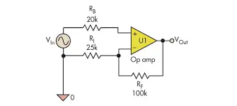
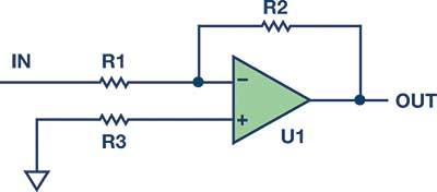
By adding a resistance (R3 in Figure 1) in the non-inverting input to ground, equal to the parallel combination of the input resistor and the feedback resistor, the impedances are made equal. Doing some algebraic manipulation, it can be shown that the error is reduced to Ioffset × Rfeedback. Because the Ioffset was 10% to 20% of Ibias, this would help in reducing the output offset error.

DC error

To reduce the input bias current on bipolar op-amps, input bias current cancellation was integrated into many op-amp designs. An example of this can be found in the OP07. With the addition of input bias current cancellation, the bias current is greatly reduced, but the input offset current can be 50% to 100% of the remaining bias current, so adding the resistor has very little effect. In some cases, adding the resistor could result in the output error actually increasing.

Noise

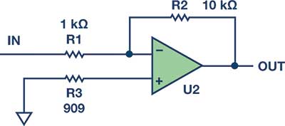
The thermal noise of a resistor is given by √4kTRB, so a 1 kΩ resistor will be 4 nV/√Hz. Adding a resistor will add noise. In Figure 2, surprisingly, even though the 909 Ω compensation resistor is the lowest value because of noise gain from that node to the output, it contributes the most noise at the Figure 2 output. Output noise due to R1 is 40 nV/√Hz, for R2, 12.6 nV/√Hz, and for R3, 42 nV/√Hz. So don’t use a resistor.

On the other hand, if the op-amp is powered from split supplies and one supply comes up before the other one, there may be latch-up problems with the ESD network, in which case it may be desirable to add some resistance to protect the part. But if used, a bypass cap should be placed across the resistor to reduce the noise contribution of the resistor.

Figure 1. Classic inverting amplifier.

Figure 1. Classic inverting amplifier.
Figure 2. Noise analysis.

Figure 2. Noise analysis.
Figure 3. What you see.

Figure 3. What you see.
Figure 4. What the electrons see.

Figure 4. What the electrons see.

Stability

All op-amps have some input capacitance, both differential and common mode. If the op-amp is connected as a follower and the impedances are balanced by putting a resistor in the feedback path, the system may become prone to oscillation. The reason is that with a large feedback resistor, the input capacitance of the op-amp, and the stray capacitance on the PC board, an RC low-pass filter (LPF) is formed. This filter causes phase shift and will reduce the phase margin of the closed-loop system. If it reduces it too much, the op-amp will oscillate.

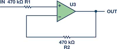
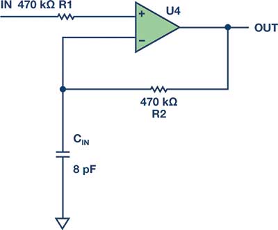
A customer was using an AD8628 CMOS op-amp in a 1 Hz, Sallen-Key low-pass filter circuit. Because of the low corner frequency, the resistors and capacitors were rather large (see Figure 3). The input resistor was 470 kΩ, so the customer put a 470 kΩ in the feedback. This resistor, in combination with the eight picofarads of input capacitance (see Figure 4), gave the customer a pole at 42 kHz.

The AD8628 has a gain bandwidth product of 2 MHz, so it still had plenty of gain at 42 kHz and it oscillated rail-to-rail. Changing the 470 kΩ resistor to a 0 Ω jumper solved the problem. So avoid large resistors in the feedback where large depends on the gain bandwidth of the op-amp. For high frequency op-amps, such as the ADA4817-1 with a gain bandwidth over 400 MHz, a 1 kΩ feedback would be large. Always read the data sheet for recommendations.

Summary

Over the years, rules of thumb are developed that serve a purpose. On a design review, it’s always good practice to look carefully at these rules and see if they are still applicable. With respect to adding a balancing resistor, if the op-amp is CMOS, JFET or bipolar with input bias current cancellation, you probably don’t need one.


Related

Recent Posts

Stackpole Introduces 1400A Busbar Shunt Resistors

2.6.2026
10

Passive Components in 2026: From Invisible Commodity to Design Parameter

2.6.2026
21

May 2026 Interconnect, Passives and Electromechanical Components Market Insights

29.5.2026
93

Passive Components Enable Safe and Reliable ADAS Architectures

28.5.2026
68

Stackpole Introduces High‑Voltage Low VCR Chip Resistors

25.5.2026
39

Industrial Passive Components Markets and Technologies 2026

21.5.2026
154

Automotive Passive Components Technology Dossier

21.5.2026
85

ESA SPCD 26 Registration Open

15.5.2026
40

Stackpole Releases Automotive Wide‑Termination Resistors

14.5.2026
44

Upcoming Events

Jun 16
16:00 - 17:00 CEST

EMC with EMC – EMC‑compliant design with electromechanical connectors

View Calendar

Popular Posts

  • Buck Converter Design and Calculation

    0 shares
    Share 0 Tweet 0
  • Boost Converter Design and Calculation

    0 shares
    Share 0 Tweet 0
  • Flyback Converter Design and Calculation

    0 shares
    Share 0 Tweet 0
  • MLCC and Ceramic Capacitors

    0 shares
    Share 0 Tweet 0
  • LLC Resonant Converter Design and Calculation

    0 shares
    Share 0 Tweet 0
  • Capacitor Charging and Discharging

    0 shares
    Share 0 Tweet 0
  • What Electronics Engineer Needs to Know About Passive Low Pass Filters

    0 shares
    Share 0 Tweet 0
  • Dual Active Bridge (DAB) Topology

    0 shares
    Share 0 Tweet 0
  • Ripple Current and its Effects on the Performance of Capacitors

    3 shares
    Share 3 Tweet 0
  • SEPIC Converter Design and Calculation

    0 shares
    Share 0 Tweet 0

Newsletter Subscription


Passive Components Blog

© EPCI - Leading Passive Components Educational and Information Site

  • Home
  • Privacy Policy
  • EPCI Membership & Advertisement
  • About

No Result
View All Result
  • Home
  • Knowledge Blog
  • Dossiers
  • PCNS

© EPCI - Leading Passive Components Educational and Information Site

This website uses cookies. By continuing to use this website you are giving consent to cookies being used. Visit our Privacy and Cookie Policy.
Go to mobile version