


The reliability and failure modes in surface mount Solid Electrolytic and Polymer Tantalum capacitors were investigated using the parts manufactured with conventional technology and flawless technology (F-Tech) that suppresses typical defects such as crystalline inclusions in the amorphous matrix of the tantalum oxide dielectric.
The paper was presented by Yuri Freeman, KEMET Electronics Corporation. USA at the 3rd PCNS 7-10th September 2021, Milano, Italy as paper No.2.1.
Solid Tantalum Capacitors Failure Modes
Failure Modes – Overview
The first solid Tantalum capacitors with a tantalum powder anode sintered in vacuum, an anodic oxide film of tantalum as the dielectric and a manganese dioxide (MnO2) cathode were invented in the early 1950s at the Bell Telephone Laboratories in the USA.1 Initially these capacitors were called Dry Electrolytic Device, and later the name was changed to Solid Electrolytic Tantalum capacitors. Similar to the liquid electrolyte cathodes in Wet Tantalum capacitors developed earlier, the MnO2 cathode supplies oxygen to the tantalum pentoxide (Ta2O5) dielectric maintaining its chemical composition under applied voltages and elevated temperatures. The chemical and phase transformations in Solid Electrolytic Tantalum capacitors are shown in Fig. 1.
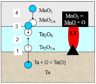
According to Fig. 1, tantalum anode extracts oxygen from the Ta2O5 dielectric enriching tantalum with oxygen Ta(O) and leaving oxygen vacancies Ta2O5-x in the dielectric in vicinity of the anode-dielectric interface (1). Under the gradient of concentration oxygen vacancies diffuse to the dielectric-cathode interface (2) where they are compensated by oxygen from the MnO2, leaving oxygen vacancies MnO2-x in the cathode (3). These oxygen vacancies are compensated by the oxygen diffusion from the distant from the dielectric part of the MnO2 cathode toward the cathode-dielectric interface (4). This sequence of the oxygen migration processes provides dynamic equilibrium in the chemical composition of the dielectric and thus stable DC characteristics, particularly DC leakage (DCL) during long-term testing and field application of these capacitors.
Additionally, the MnO2 cathode also provides strong self-healing properties to the Solid Electrolytic Tantalum capacitors due to the phase transformation into low manganese oxides (Mn2O3, Mn3O4, MnO) under the heat released in the defect sites in the dielectric that have high leakage current density (Fig. 1). The unique property of the manganese oxides is that they sharply increase resistivity as they release oxygen and transform from higher into lower manganese oxide (Fig. 2), while oxides of almost all the other metals reduce resistivity as they transform from higher to lower oxides.
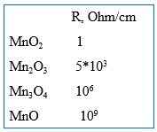
Resistive low manganese oxides block current flow through the defect sites in the dielectric, which is critical for the reliability of the Solid Electrolytic Tantalum capacitors.
The AC characteristics of Solid Electrolytic Tantalum capacitors are superior to these in Wet Tantalum capacitors where low mobility of ions in the liquid electrolyte cathode cause high equivalent series resistance (ESR) and related rapid capacitance loss with frequency, especially at low temperatures. A combination of the stable DC and AC characteristics with high volumetric efficiency in terms of charge (Q/cc) and energy (E/cc) and high reliability (the cumulative failure rate is decreasing with time) provided steady increase in applications of Solid Electrolytic Tantalum capacitors since their mass manufacturing was initiated in the US by Sprague Electric in 1954 and until early 2000s.
Polymer Tantalum capacitors with conductive polymer cathode were developed by NEC Corporation, Japan, and introduced to the market in middle 1990’s.2 Similar to the Solid Electrolytic Tantalum capacitors, Polymer Tantalum capacitors have a sintered tantalum powder anode and anodic oxide film of tantalum as the dielectric; however, their cathode is made of inherently conducting polymer typically made of poly(3,4-ethylenedioxytheophene) (PEDOT). The conductivity of PEDOT is higher than conductivity of MnO2, providing lower ESR, and thereby better capacitance stability with frequency and ripple current capability in Polymer Tantalum capacitors in comparison to these characteristics in Solid Electrolytic Tantalum capacitors.
The time-to-failure distribution at accelerated testing of Polymer Tantalum capacitors is different fromthat in Solid Electrolytic Tantalum capacitors.3,4 Typically, there are no or very few failures at the earlier stages of the testing and then majority of the capacitors fail within relatively short period of time (wear-out region). Though as presented in Refs.3,4 median times to failure in Polymer Tantalum capacitors at normal application conditions were lengthy, the wear-out performance of these capacitors was concerning, especially, in high reliability applications.
The typical failure mode inSolid Electrolytic and Polymer Tantalum capacitors is low insulation resistance or a short. The hypothesis about ignition and burning tantalum failure mode in SMD type Solid Electrolytic Tantalum capacitors was initially presented by Prymak5 after more than 40 years of broad applications of these capacitors without any ignition and burning reported. According to Ref.5 the heat released at breakdown of these capacitors causes microcracks in the Ta2O5 dielectric where exposed tantalum anode is ignited by oxygen from the reducing MnO2 cathode. Since PEDOT cathode doesn’t have active oxygen in its molecular structure, no ignition and burning of tantalum anodes takes place at the breakdown event in Polymer Tantalum capacitors (“benign” failure mode).
To prove the hypothesis about ignition and burning tantalum failure mode in Solid Electrolytic Tantalum capacitors and no ignition failure mode in Polymer Tantalum capacitors, the reverse polarity voltage was continuously increased on these capacitors until Solid Electrolytic Tantalum capacitors ignited at reverse voltage about the twice rated voltage and the voltage was disconnected. It is well known that Tantalum capacitors are polar with breakdown voltage at reverse polarity much less than the rated voltage. In this case the ignitions reported in Ref.5 could be caused by flammable epoxy compound in external encapsulation and could be observed on Polymer Tantalum capacitors as well with slight additional increase of the reverse voltage and related current and heat.
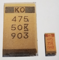
To reduce the risk of failure in Solid Electrolytic Tantalum capacitors, 50% derating (Va/Vr = ½) was recommended.6 and accepted for most applications. The 50% derating causes about 10x loss in volumetric efficiency due to a combination of the thicker dielectric and lower anode surface area since larger tantalum particles, coarser tantalum powders, are needed to form the thicker dielectric. As an example, Fig. 3 shows Tantalum capacitors B-case 4.7 uF – 25 V (no de-rating) and D-case 4.7 uF – 50 V (50% de-rating).
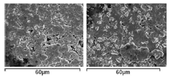
Besides the loss in volumetric efficiency, increasing thickness of the dielectric due to de-rating can cause larger density and size of the defect sites in the dielectric (Fig. 4) that affect the reliability of Tantalum capacitors [7].
The loss in volumetric efficiently and fear of ignition and burning tantalum failure mode, which now dominates online publications, resulted in decline in general applications of Solid Electrolytic Tantalum capacitors including the applications where high reliability and environmental stability of these capacitors are most needed. At the same time, the applications of Polymer Tantalum capacitors were increasing; however, at much lower rate in comparison to that in Ceramic and Film capacitors. The wear-out failure mode was one of the major factors slowing applications of Polymer Tantalum capacitors.
In this paper the reliability and failure mode in surface mount Solid Electrolytic and Polymer Tantalum capacitors were investigated on the parts manufactured with conventional technology and flawless technology (F-Tech).7 Flawless technology suppresses typical defects such as crystalline inclusions in the amorphous matrix of the Ta2O5 dielectric that continue growth during the capacitor testing and field applications eventually causing cracks in the dielectric and capacitor failures. The critical part of the F-Tech is reducing bulk oxygen content in tantalum anodes that promotes formation of the crystalline seeds at the anode-dielectric interface. Reducing the oxygen content in tantalum anodes in F-Tech is achieved either by treatment of the sintered in vacuum tantalum anodes in deoxidizing atmosphere, such as magnesium vapor, or by sintering of the pressed tantalum powder pellets in a deoxidizing atmosphere (F-Tech with deox-sintering).
ACCELERATED LIFE TESTS
Experimental
The broadly used in the end-electronics KEMET X-case 6.8μF, 50V Solid Electrolytic Tantalum capacitors and H-case 220μF, 25V Polymer Tantalum capacitors manufactured with conventional technology and F-Tech were investigated. The accelerated tests were performed. with 1 A fuse connected to the individual parts and the failure was indicated by the blown fuse. In the failed parts the epoxy compound and the external layers of silver, carbon and cathode were stripped in diluted solutions of nitric and sulfuric acids to reveal fault sites in the dielectric. SEM and EDX spectroscopy were used to analyze the structure and chemical composition of the fault sites and surrounding areas in the dielectric of the failed Solid Electrolytic and Polymer Tantalum capacitors. The details of the capacitor manufacturing, conditions of the accelerated tests, calculations of the failure rates and SEM and EDX analysis were presented in [8].
Results and Discussion
Accelerated Weibull test of X-case 6.8μF, 50V Solid Electrolytic Tantalum capacitors manufactured with conventional technology and F-Tech was performed at 70V (Va/Vr = 1.4) and 85°C. The cumulative percent of failed vs time and failure rate vs. time in these capacitors are shown in Fig. 5.
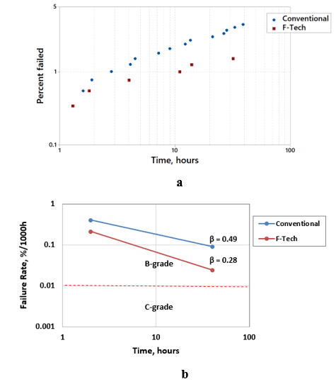
Fig. 5. Cumulative percent of failed (a) and failure rate (b) versus time at Weibull test at 70V and 85°C of X-case 6.8μF, 50V Solid Electrolytic Tantalum capacitors manufactured with conventional technology and FTech.
As one can see in Fig. 5a, the percent of failed parts and failure rates are lower in capacitors manufactured with F-Tech in comparison to these the in the capacitors manufactured with conventional technology. Significant reduction in the failure rate in Solid Electrolytic Tantalum capacitors manufactured with F-Tech was also verified by the end-user in high reliability application.9 At the same time the failure rate is decreasing with time (β<1) in Solid Electrolytic Tantalum capacitors manufactured with conventional technology and with F-Tech (Fig. 5b), which is typical for these capacitors within Weibull limitation Va/Vr ≤ 1.527 at 85°C. The lower β in the capacitors manufactured with F-Tech indicates steeper failure rate decrease with time and, thereby, shorter additional time needed to achieve C-grade (0.01%/1000h) or D-grade (0.001%/1000h) failure rates required for the high-reliability applications.
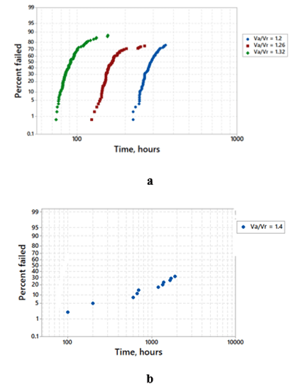
The accelerated test of the H-case 220μF, 25V Polymer Tantalum capacitors manufactured with conventional technology and F-Tech was performed at several Va/Vr and 105°C. Fig. 6 shows cumulative percent of failed capacitors as a function of time.
Fig 6a shows wear-out behavior in Polymer Tantalum capacitors manufactured with conventional technology: most of the parts fail withing relatively short time intervals and these intervals are shifting to earlier times with increasing Va/Vr. In contrast to that, there is no wear-out in Polymer Tantalum capacitors manufactured with F-Tech (Fig. 6b) even at higher Va/Vr and much longer time than these used for Polymer Tantalum capacitors manufactured with conventional technology. Comparison of Fig. 5 and Fig. 6 shows early failures at the accelerated testing of Solid Electrolytic Tantalum capacitors while practically no early failures in Polymer Tantalum capacitors. The difference in the time-to-failure performance in these capacitors can be related to the difference between the high temperature pyrolytic deposition of the MnO2 cathode in Solid Electrolytic Tantalum capacitors and low temperature deposition of the polymer cathode in Polymer Tantalum capacitors. The temperature accelerates degradation processes, particularly, growth of the crystalline inclusions in the amorphous matrix of the Ta2O5 dielectric, resulting in earlier failures in Solid Electrolytic Tantalum capacitors in comparison to that in Polymer Tantalum capacitors. By eliminating crystalline seeds at the dielectric-anode interface, F-Tech suppresses crystallization process in the Ta2O5 dielectric reducing failure rate in both types of solid Tantalum capacitors and eliminating wear-out performance in Polymer Tantalum capacitors.
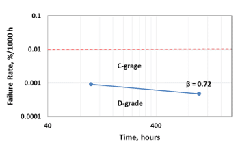
Using the data presented in Fig. 6b, the failure rate in Polymer Tantalum capacitors manufactured with F-Tech was estimated for 100 h and 1000 h of accelerated testing (Fig. 7).
As one can see in Fig. 7, Polymer Tantalum capacitors manufactured with F-Tech have the lowest D-grade failure rate, which is decreasing with time similar to that in Solid Electrolytic Tantalum capacitors.
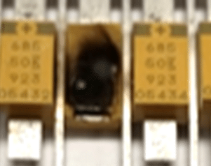
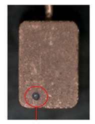
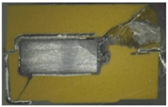
The typical failure mode in Solid Electrolytic and Polymer Tantalum capacitors manufactured with conventional technology and F-Tech is low insulation resistance or short. The failed short Solid Electrolytic Tantalum capacitors usually have black marks on their surface (Fig. 8a) while typically there are no black marks on the surface of the failed short Polymer Tantalum capacitors. The fault sites in the dielectric were revealed in the failed short Solid Electrolytic after the epoxy compound and external layers of silver, carbon and cathode were chemically stripped (Fig. 8b). Similar fault sites in the dielectric were revealed in failed short Polymer Tantalum capacitors.
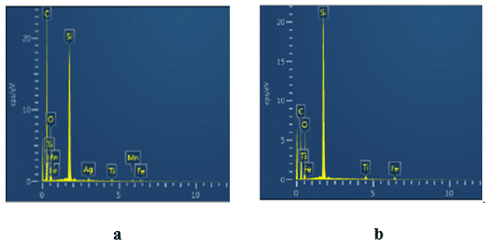
The chemical composition inside and outside the fault sites in the dielectric in the failed short Solid Electrolytic Tantalum capacitors was investigated by EDX spectroscopy (Fig. 9).
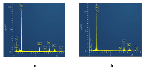
As one can see in Fig. 9, the spectrums inside (Fig. 9a) and outside (Fig. 9b) the fault site in the dielectric have peaks of tantalum, oxygen and residual carbon and silicon from the epoxy compound and external layers. At the same time the spectrum inside the fault site in the dielectric has additional peaks of manganese. Since MnO2 cathode was stripped from the dielectric, the peaks of manganese and oxygen in Fig. 9a indicate chemically stable low magnesium oxides: Mn2O3, Mn3O4 and MnO that form on the surface of the fault site in the dielectric due to reduction of the MnO2 cathode under the heat released in breakdown channel. The EDX spectroscopy was also performed inside and outside the fault sites in the dielectric of the failed short Polymer Tantalum capacitors. Both inside and outside spectrums were identical to shown in Fig. 9b with peaks of tantalum, oxygen, and residual silicon and carbon from the epoxy compound and the external layers on the surface of the dielectric.
Though oxygen was released from MnO2 cathode when it was reduced into low manganese oxides at breakdown event and at the same time micropores were formed in the fault sites in the dielectric exposing tantalum anode, there were no signs of ignition and burning tantalum in failed short Solid Electrolytic Tantalum capacitors. Outside the small fault sites tantalum anode was tightly covered with thick layer of undamaged anodic tantalum oxide (Fig. 10).
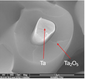
Principally different structure from the one shown in Fig. 10 was observed when porous tantalum anode was ignited with a burner. During the burning tantalum anodes convert into foamy polycrystalline tantalum pentoxide and this type of the anode structure also has not been observed in any of the failed short SMD type Tantalum capacitors.
Presented in Fig. 9,10 is evidence that low manganese oxides that form on the fault sites in the dielectric under the heat released at breakdown tightly seal the microcracks in the dielectric, preventing reaction between the exposed tantalum anode and oxygen released from the reduced MnO2 cathode and, thereby, preventing ignition and burning tantalum in failed short Solid Electrolytic Tantalum capacitors.
The heat released at breakdown of the SMD type Solid Electrolytic and Polymer Tantalum capacitors propagates from the fault site in the Ta2O5 dielectric through the epoxy compound toward the external surface of the capacitor (Fig. 11).
For the same amount of energy stored in the capacitor, the amount of heat released at breakdown is larger in failed short Solid Electrolytic Tantalum capacitors in comparison to that in Polymer Tantalum capacitors due to resistant low manganese oxides in the fault sites in the dielectric. As a result of the larger amount of heat, failed short Solid Electrolytic Tantalum capacitors typically have black marks on their external surface while typically there are no black marks on the surface of the failed short Polymer Tantalum capacitors.
Chemical composition of the epoxy compound inside and outside the black marks on the surface of the failed short Solid Electrolytic Tantalum capacitor was investigated with EDX spectrometry (Fig. 12).
As one can see in Fig. 12 the major difference between the epoxy compound inside the black mark (Fig. 12a) and in undamaged yellow color epoxy compound outside the black mark (Fig. 12b) is high carbon content in the black mark indicating local carbonization of the epoxy compound under the heat released at breakdown.
The carbonization process consumes heat and protects from burning of the epoxy compound. In fact, composites based on epoxy resins used in SMD type Tantalum capacitors, have demonstrated good protective properties in buffering of fire .12 Increasing the current in failed short Solid Electrolytic Tantalum capacitors can eventually increase the temperature up to the point where the epoxy compound ignites and burns; though, no ignition and burning have been observed at normal conditions of the accelerated testing. Similar ignition and burning of the epoxy compound can occur in any SMD type electronic component that failed short and then subjected to unrestricted current. The epoxy compound used in surface mount Tantalum capacitors is flame retardant and meets UL 94 V-0 flammability standard requiring not more than 10 seconds of flaming after the burning is initiated.
CONCLUSIONS
Conclusions
The results presented in this paper show strong impact of technology on reliability of Solid Electrolytic and Polymer Tantalum capacitors. Solid Electrolytic Tantalum capacitors manufactured with flawless technology (F-Tech) have significantly lower failure rate in comparison to the failure rate in the capacitors manufactured with conventional technology. Polymer Tantalum capacitors manufactured with F-Tech have the lowest failure rate, which is decreasing with time of the accelerated testing (no wear-out) similar to that in Solid Electrolytic Tantalum capacitors.
There is no ignition and burning tantalum in failed short SMD-type Solid Electrolytic Tantalum capacitors. The low manganese oxides, which form on the surface of the fault sites in the dielectric under the heat released at breakdown, seal microcracks in the dielectric, preventing the reaction between the exposed tantalum anode and the oxygen released from reduced MnO2 cathode and, thereby, eliminating ignition and burning tantalum.
The black marks typically observed on the surface of the failed short Solid Electrolytic Tantalum capacitors are the areas of the epoxy compound carbonized under the heat propagated from the fault sites in the dielectric at the breakdown event. For the same amount of energy stored in the capacitor, more heat is generated in failed short Solid Electrolytic Tantalum capacitors due to the high resistance low manganese oxides covering the fault sites in the dielectric.
No ignition and burning of the epoxy compound are typically observed when SMD-type Solid Electrolytic and Polymer Tantalum capacitors fail short at normal conditions of the accelerated testing or during field applications. The epoxy compounds used in manufacturing of SMD-type solid Tantalum capacitors and other types of the electronic components is flame retardant and meets UL 94 V-0 safety standard.
Reliable and efficient SMD-type Tantalum capacitors manufactured with F-Tech allow optimal choices to the designers of the end-electronic devices depending on the specific conditions of their applications. Polymers Tantalum capacitors are preferable in applications where low ESR and, thereby, higher capacitance stability with frequency and ripple current capability are most critical. Solid Electrolytic Tantalum capacitors are preferable in applications where long-term stability of the AC and DC characteristics in harsh environmental conditions, such as a combination of the dry air or vacuum and elevated temperatures, are most critical.
Acknowledgments
The authors thank Clemson University’s Dr. Igor Luzinov and KEMET’s Barry Reeves, Steve Hussey, Chris L. Guerrero, John Ols, Steve Brooks, Cynthia Prince, Kevin P. Hanley, Joshua Reid, and Craig Busby for their help with making and testing the parts and valuable discussions.
References
1. Haring, H. E.; Taylor, R. L. Dry electrolitic device. US Patent 3,166,693, 1965.
2. Kobayashi, A.; Nishiyama, T.; Watanabe, K.; Nakata, T.; Morimoto, K. 10th European Passive Components Symposium, Nice, France (1996), Nice, France (1996), 1996.
3. Paulsen, J.; Reed, E. 1st Capacitor and Resistor Technology Symposium (CARTS), St. Petersburg, FL (2001), St. Petersburg, FL (2001), 2001; p 265.
4. Paulsen, J.; Reed, E.; Kelly, J. 24th Capacitor and Resistor Technology Symposium (CARTS), San Antonio, TX (2004), San Antonio, TX (2004), 2004; p 114.
5. Prymak, J. 21st Capacitor and Resistor Technology Symposium (CARTS), St. Petersburg, FL (2001), St. Petersburg, FL (2001), 2001; p 25.
6. Prymak, J. 23rd Capacitor and Resistor Technology Symposium (CARTS), Scottsdale, AZ (2003), Scottsdale, AZ (2003), 2003; p 278.
7. Freeman, Y., Tantalum and Niobium-based Capacitors. Springer: Cham, Switzerland, 2018; p 120.
8. Freeman Y., Lessner P., Luzinov I., ECS J. Solid State Sci. Technol. 2021, 10, 045007.
9. Winkel, W.; Rich, E. 34th Symposium for Passive Electronic Components, Santa Clara, CA (2014), Santa Clara, CA (2014), 2014; p 175. 10. Camino, G.; Tartaglione, G.; Frache, A.; Manferti, C.; Costa, G., Thermal and combustion behaviour of layered silicate-epoxy nanocomposites. Polymer Degradation and Stability 2005,90 (2), 354-362.
This article is shortened version of original paper available at the link below or pdf download.


