Passive Components Blog
No Result
View All Result
  • Home
  • NewsFilter
    • All
    • Aerospace & Defence
    • Antenna
    • Applications
    • Automotive
    • Capacitors
    • Circuit Protection Devices
    • electro-mechanical news
    • Filters
    • Fuses
    • Inductors
    • Industrial
    • Integrated Passives
    • inter-connect news
    • Market & Supply Chain
    • Market Insights
    • Medical
    • Modelling and Simulation
    • New Materials & Supply
    • New Technologies
    • Non-linear Passives
    • Oscillators
    • Passive Sensors News
    • Resistors
    • RF & Microwave
    • Telecommunication
    • Weekly Digest

    Samsung Electro-Mechanics Releases High-Capacitance MLCCs for AI Server Applications

    Samsung Electro-Mechanics Releases 165C Automotive 0806 Size Power Inductors

    Coupled Inductors Circuit Model and Examples of its Applications

    Würth Elektronik Introduces LTspice Models for ESD Products

    Capacitor Ripple Current Testing: A Design Consideration

    TDK Releases 0201 High-Frequency Smallest Inductors

    Coilcraft Extends Air Core RF Inductors

    Bourns Releases Automotive 1W Flyback Transformer

    Wk 20 Electronics Supply Chain Digest

    Trending Tags

    • Ripple Current
    • RF
    • Leakage Current
    • Tantalum vs Ceramic
    • Snubber
    • Low ESR
    • Feedthrough
    • Derating
    • Dielectric Constant
    • New Products
    • Market Reports
  • VideoFilter
    • All
    • Antenna videos
    • Capacitor videos
    • Circuit Protection Video
    • Filter videos
    • Fuse videos
    • Inductor videos
    • Inter-Connect Video
    • Non-linear passives videos
    • Oscillator videos
    • Passive sensors videos
    • Resistor videos

    Coupled Inductors Circuit Model and Examples of its Applications

    Inductor Resonances and its Impact to EMI

    Highly Reliable Flex Rigid PCBs, Würth Elektronik Webinar

    Causes of Oscillations in Flyback Converters

    How to design a 60W Flyback Transformer

    Modeling and Simulation of Leakage Inductance

    Power Inductor Considerations for AI High Power Computing – Vishay Video

    Coupled Inductors in Multiphase Boost Converters

    VPG Demonstrates Precision Resistor in Cryogenic Conditions

    Trending Tags

    • Capacitors explained
    • Inductors explained
    • Resistors explained
    • Filters explained
    • Application Video Guidelines
    • EMC
    • New Products
    • Ripple Current
    • Simulation
    • Tantalum vs Ceramic
  • Knowledge Blog
  • Suppliers
    • Who is Who
  • Events
No Result
View All Result
Passive Components Blog
No Result
View All Result

RF Ceramic Capacitors Characteristics

3.10.2022
Reading Time: 7 mins read
A A

This KEMET technical blog explains What are RF ceramic capacitors, its construction, key characteristics and applications.

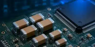
Every year, over four trillion ceramic capacitors are manufactured for applications ranging from toys, wearable technology, and electric vehicles to satellites. These capacitors perform a broad range of functions such as decoupling, filtering, transient voltage suppression, and many more.

RelatedPosts

Tantalum Capacitor History

Understanding the Influence of ESR and Ripple Current for the Capacitor Selection

Resonant MLCC OBC Application Guide

For the vast majority of these applications, standard Base Metal Electrode (BME) ceramic technology uses nickel as the internal electrode.  In fact, over 99% of ceramic capacitors shipped today use nickel electrode technology.

However, there is a subset of applications used today that operate at much higher frequencies, and standard nickel electrode technology is not suitable. This article provides insight into some of the key characteristics of RF capacitors and why they are important for high-frequency applications.

What is RF?

Before we define what an RF capacitor is, we need to provide some background on RF. RF stands for “Radio Frequency” and refers to the oscillation rate of an AC voltage, current, or electromagnetic waves in an electronic device or medium. Today, almost all electronic devices use alternating voltages and currents, ranging from 50Hz to 100s of GHz. RF is a very broad term and refers to frequencies when the AC voltages are above 20kHz. However, in the context of RF applications and RF capacitors, RF is usually referred to with frequencies starting above a few MHz and up. Sometimes, the term “RF” and “High Frequency” are used interchangeably when referring to high-frequency components and applications.

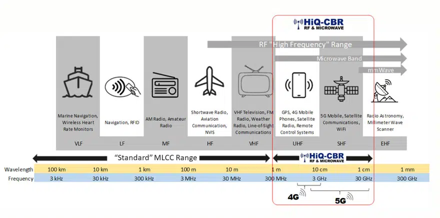
The RF frequency spectrum can be divided into multiple regions (bands) based on the frequency range and target applications. The RF “High Frequency” range can be divided into the “Microwave Band” which ranges from 300MHz to 300GHz and the mmWave (millimeter wave) band which begins at 28GHz. As frequency increases, the wavelength decreases as shown in the figure below. The term mmWave derives its name from the wavelength of the electromagnetic wave being measured in millimeters.  

Figure 1 – RF ceramic capacitors frequency spectrum; source: KEMET

Why go to higher frequency ranges?

There are key advantages when increasing the frequency of applications to go higher and higher. By increasing the frequency, designers can make better use of the frequency spectrum allowing more devices to be wireless without causing interference. In addition, increasing the frequency allows for higher bandwidth. Thus, increasing data transmission.

However, there are disadvantages to higher frequencies. These include shorter ranges, signals blocked by dense objects, and signals affected by weather conditions. This is why higher frequency mmWave 5G technology will require more cellular base stations in dense population areas.

RF Capacitor Applications

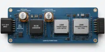
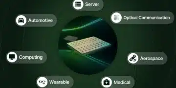
RF capacitors are used for various functions such as DC blocking, bypass, filtering, and impedance matching. Common applications include the following:

  • RF power amplifiers (PA)
  • Cellular base stations (4G, 5G)
  • Wireless LAN
  • Telecommunication Networks
  • GPS
  • Keyless entry systems
  • Bluetooth
  • Automotive V2X, Safety Systems, Power Train, Communication Systems

What makes RF capacitors different?

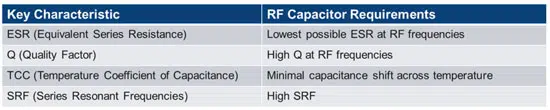
There are four key characteristics of capacitors needed for RF applications.

Very low Equivalent Series Resistance (ESR) at high frequencies:

This is the resistance of the capacitor which includes resistance due to losses in the dielectric and electrodes. This is important because ESR is directly related to power dissipation in the form of heat. Higher ESR can cause excessive heating in the capacitor, and RF capacitors must have the lowest possible ESR at high frequencies.

Power Dissipation = i 2  * ESR 

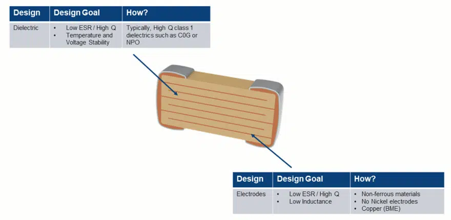
To achieve low ESR in a ceramic capacitor, the dielectric and electrodes must be optimized to have the lowest possible losses. For the dielectric, RF capacitors are almost always a Class I C0G/NPO dielectric material due to their very low loss. 

Figure 2 – Resistance of a 100mm wire made from copper and nickel.

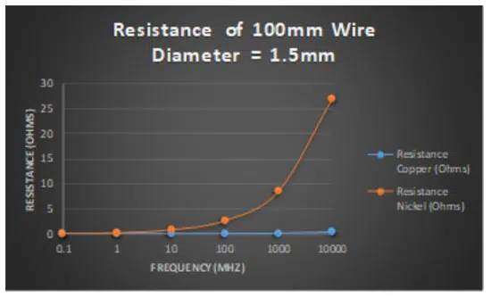
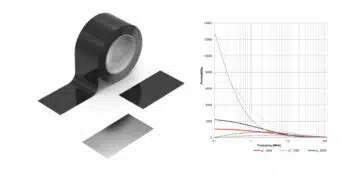
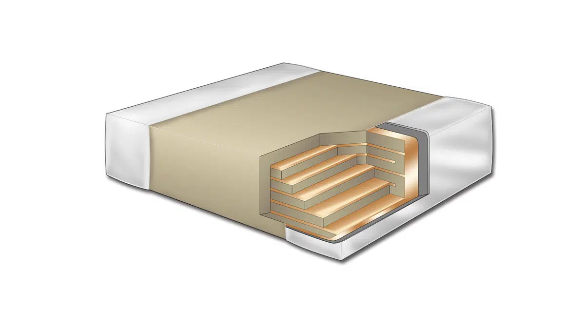
Even more important is the choice of the inner electrode material. Figure 2 shows a comparison of resistance between a 100mm wire made from nickel and the same wire made from copper. The graph shows that as frequency increases above 10MHz, the resistance of the nickel wire starts increasing dramatically while the resistance of the copper wire remains relatively flat. For this reason, copper is the material of choice for Base Metal Electrode RF capacitors.   

High-Quality Factor (Q) at high frequencies:

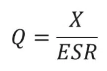
Q represents the efficiency of the capacitor and represents the ratio of energy stored in the capacitor to the energy dissipated as thermal losses due to the equivalent series resistance (ESR).  Q is directly related to ESR because lower ESR means higher Q since it’s inversely proportional. RF capacitors have very high Q due to their low capacitance and very low ESR.  Therefore, RF capacitors are often referred to as High Q capacitors.

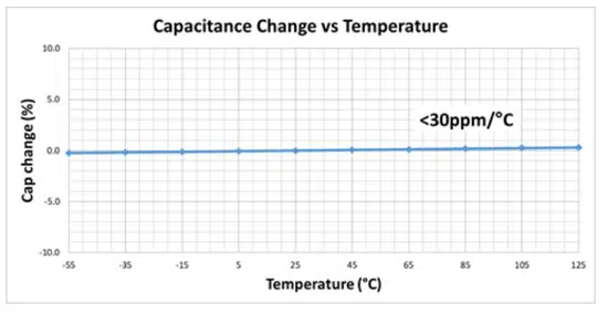
Capacitance stability vs temperature:

Since RF capacitors are often used for tuning and impedance matching applications, capacitance stability versus temperature is critical. Any change in capacitance with temperature can result in the circuit detuning or becoming unmatched.

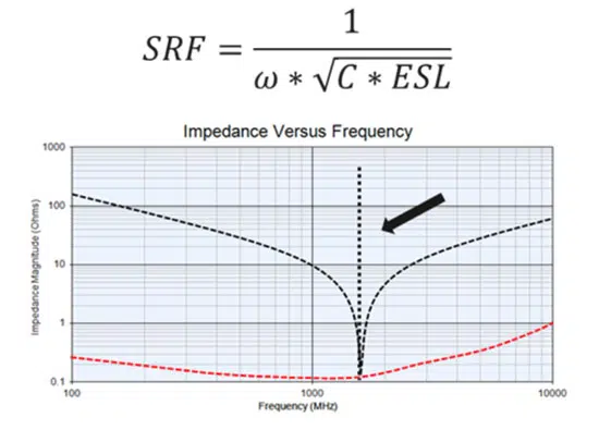
Series Resonant Frequency (SRF):

SRF shows where the total impedance is no longer capacitive and begins an upward trend.  This is known as the inductive region of the impedance curve and is a direct result of the capacitor’s Equivalent Series Inductance (ESL).  For some applications, it is necessary to stay well below the SRF, so RF capacitors need to have as high an SRF as possible.  

Figure 3 – Capacitance change vs temperature of a Class 1 RF ceramic capacitor
Figure4 – Impedance versus frequency of a Class 1 RF ceramic capacitor showing the SRF.

What is RF ceramic capacitor?

Knowing the four key characteristics of an RF ceramic capacitor, a definition can be provided.

Definition: An RF ceramic capacitor is a ceramic capacitor that’s “characteristics” are optimal at RF frequencies.

Therefore, for RF capacitors, materials are chosen, and designs are optimized so that the capacitor’s characteristics are optimal at higher frequencies.

Table 1. Key RF ceramic capacitors characteristics and requirements; source: KEMET
Figure 5. RF ceramic capacitor construction; source: KEMET

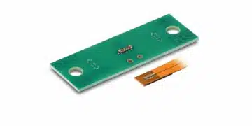
HiQ RF Ceramic Capacitors for RF and Microwave Applications

Example of specific RF ceramic capacitor is KEMET’s HiQ CBR RF Capacitor Series with a copper electrode BME (Base Metal Electrode) system that offers ultra-low ESR and High Q in the VHF, UHF, and microwave frequency bands. Low ESR allows for higher RF currents which are ideal for various applications. Available in both commercial and automotive grades, these capacitors exhibit very low ESR and high Q along with high SRF making them ideal for applications ranging from 1 MHz to 50 GHz.  

Table 2. KEMET RF ceramic capacitors specification table

Related

Source: KEMET

Recent Posts

Samsung Electro-Mechanics Releases High-Capacitance MLCCs for AI Server Applications

21.5.2025
14

Coupled Inductors Circuit Model and Examples of its Applications

21.5.2025
6

Würth Elektronik Introduces LTspice Models for ESD Products

21.5.2025
9

Littelfuse Gate Driver Integrates Diode and Current Limit Resistor in Compact IC

21.5.2025
3

Capacitor Ripple Current Testing: A Design Consideration

21.5.2025
8

Inductor Resonances and its Impact to EMI

16.5.2025
30

Developing Low Inductance Film Capacitor using Bode 100 Analyzer

15.5.2025
40

Causes of Oscillations in Flyback Converters

15.5.2025
22

YAGEO Extends Rectangular Aluminum Electrolytic Capacitor Family

15.5.2025
49

Dr. Tomas Zednicek Vision for Europe 2025 Passive Electronics Market

14.5.2025
45

Upcoming Events

May 28
16:00 - 17:00 CEST

Power Over Data Line

View Calendar

Popular Posts

  • Buck Converter Design and Calculation

    0 shares
    Share 0 Tweet 0
  • What is a Dielectric Constant and DF of Plastic Materials?

    4 shares
    Share 4 Tweet 0
  • Flyback Converter Design and Calculation

    0 shares
    Share 0 Tweet 0
  • Boost Converter Design and Calculation

    0 shares
    Share 0 Tweet 0
  • LLC Resonant Converter Design and Calculation

    0 shares
    Share 0 Tweet 0
  • Ripple Current and its Effects on the Performance of Capacitors

    3 shares
    Share 3 Tweet 0
  • SEPIC Converter Design and Calculation

    0 shares
    Share 0 Tweet 0
  • How to Design an Inductor

    0 shares
    Share 0 Tweet 0
  • DCL Leakage Current Characteristics of Capacitors

    0 shares
    Share 0 Tweet 0
  • Samsung Electro-Mechanics Releases High-Capacitance MLCCs for AI Server Applications

    0 shares
    Share 0 Tweet 0

Newsletter Subscription


Passive Components Blog

© EPCI - Leading Passive Components Educational and Information Site

  • Home
  • Privacy Policy
  • EPCI Membership & Advertisement
  • About

No Result
View All Result
  • Home
  • Knowledge Blog
  • Premium Suppliers

© EPCI - Leading Passive Components Educational and Information Site

This website uses cookies. By continuing to use this website you are giving consent to cookies being used. Visit our Privacy and Cookie Policy.
Go to mobile version