


This article written by Vladimir Azbel, independent consultant on tantalum capacitors, Israel, discusses how tantalum capacitor reliability and leakage current can be evaluated and impacted already from the anode stage by its proper design and characterization. The early-stage prediction of capacitor reliability and leakage current may increase the final tantalum capacitor confidence level and save considerable manufacturing costs.
The article was edited by Tomas Zednicek, EPCI European Passive Components Institute, Czech Republic
I. Introduction
Tantalum capacitors are highly valued for their small size, high capacitance, and reliability, making them ideal for use in modern electronic devices and driving their growth in global markets. In addition, the demand for tantalum is expected to increase in the next 10 years due to the rapid growth of the aviation and aerospace industries. Especially in these segments, reliability and lifetime prediction are the paramount requirements.
Tantalum Capacitor Anode – The basis and the first stage in the production
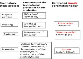
The final tantalum capacitors’ quality, its capacitance (CAP) and leakage currents (DCL) parameters can be predicted already at the stage of tantalum anode (the first capacitor electrode) – see Figure 1. Development of an appropriate tantalum anode manufacturing control methods may significantly improve the overall capacitor yield, reduce tantalum raw material losses and financial costs.
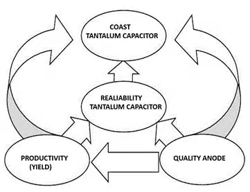
CAP and DCL are the important factors in the reliability of capacitors, and they must be carefully tested to ensure that they satisfy the design requirements, and the final capacitor will pass all reliability tests. In the design of a tantalum capacitor, the anode plays a critical role (see Fig. 1).
In conventional tantalum capacitor manufacturing CAP and DCL parameters are determined already at the anode stage by wet testing, however despite the CAP and DCL obtained by anode wet testing are within acceptable limits set by the manufacturer for its further use in production, they do not necessarily relate and guarantee reliability of the final tantalum capacitors.
One of the reasons for the difference is related to the test conditions under which the DCL is determined.
Essential tantalum capacitor reliability test is accelerated Life-Test (LT) with long-term exposure to temperature and voltage (current), which, according to most researchers, can initiate aging processes in the anode, which is the cause of DCL degradation. It is practically impossible to carry out such a check directly on the anode by of electrical characteristics.
To accelerate the aging of the anode, tantalum capacitor manufacturers expose it to an artificial aging process, to estimate its DCL values at LT. The anode is exposed to artificial aging at a temperature of 400°C for 30 minutes in the air, followed by reformation, and the process is controlled by DCL, comparing their values after artificial aging and reformation with the initial values.
It is important to note that artificial aging results are commonly used by developers to predict aging in long-term tests such as the LT. However, the applied method of DCL control, after artificial aging of the anode, does not provide information necessary for LT prediction neither yield improvements.
It is important to note that all existing methods for controlling anode aging are based on definition of tantalum capacitors’ electrical properties that may be dependent to specific applications, operating conditions, or custom requirements.
The aging process of the anode, is an indicator of the loss of structural stability and the risk of its irreversible changes, leading to a change in electrical and mechanical properties.
The purpose of the work is to propose a method that allows tantalum capacitor designers and process engineers to control the anode aging process by mechanical properties that unlike the conventional methods may be related to DCL and reliability prediction of the final tantalum capacitor.
II. Anode Mechanical Properties Evaluation
Consider what an anode represents.
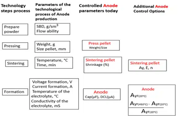
As it can be seen from the production technological scheme in Fig. 2, tantalum anode is a powder metallurgy metal product. CAP and DCL of the anode are formed in accordance with the technological parameters depending to the final capacitor requirements (Fig. 2). These design parameters are naturally linked with a certain type of morphology of its porous structure responsible for capacitance, and of the microstructure in the neck area, responsible for DCL values.
As a metal product of powder metallurgy, the anode properties can be controlled by mechanical characteristics, whose values depend on the same structure that determines its CAP and DCL.
Today, anode stability, its properties and impact to long-term temperature ageing is estimated by wet CAP and DCL measurements, as noted above.
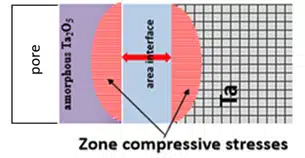
Degradation of tantalum capacitors’ DСL during LT, according to many researchers, is associated with aging processes, leading to irreversible changes in the structure caused by the relaxation of internal stresses, caused point defects, oxides, and elastic stresses in the volume of the anode, created during its production. The reason for the internal stresses in the anode is illustrated by the model below.
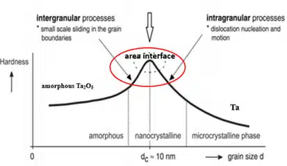
According to the model, the anode neck is presented in the form of a composite consisting of sintered porous tantalum, a film of amorphous oxide Ta2O5, and an interface between Ta and an amorphous Ta2O5 film (see Fig. 3). All three materials that make up the anode neck differ in their mechanical characteristics (see figure 3b), and in the process of creating amorphous Ta2O5, compressive stresses arise (see the diagram in the figure 3a), which leads to the risk of aging. How high the risk of aging depends on the amount of residual (internal) stress in that composite material.
The model explains how internal stresses of such a sandwich are dependent to the anode manufacturing technological process.
The aging of metals, to which the anode belongs, with long-time exposure to temperatures, leads to an increase in the risk of irreversible changes in its structure, which, on the one hand, appears itself in the degradation of the DCL during the LT, and on the other hand, from the above, it can be controlled by means of mechanical characteristics.
The use of mechanical characteristics, as an alternative method of controlling the anode aging, will make it possible to check the presence of a correlation between tantalum capacitor aging processes, its DLC during LT and the anode subjected to the temperature conditions of the LT. An estimate of the anode aging process by its mechanical characterization, will make it possible to predict behavior of the final tantalum capacitors’ DCL during the LT.
III. Experiment
To test the possibility of using the proposed method to predict DCL life-time degradation, tantalum capacitor samples of the same design, made by the same technological process from 5 different batches were used.
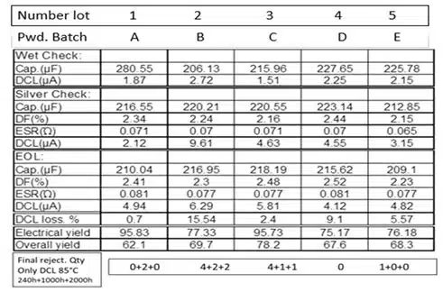
The design used 50kCV powder produced by two leading manufacturers (see Table. 1). All 5 lots passed all electrical tests: Wet test; Silver check; Final test; Life test. See electrical test data in Table 1. Note: Press pellets from all batches of powder were sintered in one run.
Experiment results:
- Wet Check, Silver Check, and Final test; were the same in all lots.
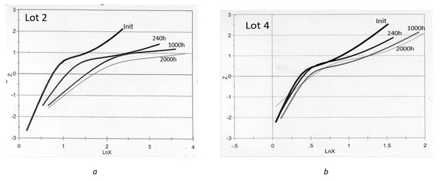
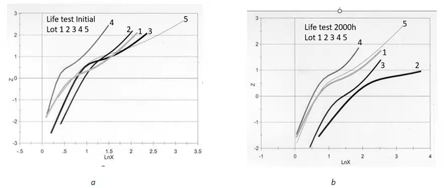
- In the reliability test, the original DCL had a very close bimodal character. Approximation and mean value of the median in all batches. See diagram 3.
- But the final DCL after 2000h. were different. See table graphs in Figures 4. And 5.
For the experiment, mechanical properties of tantalum capacitor anodes were evaluated and compared to LT performance.
Key parameters that control the mechanical properties of the material – tantalum anode – can be determined from the stress-strain curve (see Fig.6 ). These are:
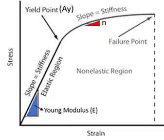
- yield strength (Ay)
- Young’s modulus (E)
- exponential hardening coefficient (P)
To obtain the stress-strain curve, the anode was compressed on INSTRONG machine with the stress-strain curve (SS curve) recorded (see Fig.6.). According to this curve, the values of the characteristics Ay, E, and P are determined. In the case of porous materials testing, these characteristics are related to the morphology of the porous structure and the microstructure of the material, see APPENDIX.
To control the aging of the anode, according to the mechanical characteristics, the SS curve of the anode is determined at room temperature, before and after exposure at the temperature of artificial aging. A change in the mechanical characteristics of the anode indicates irreversible changes in its structure after artificial aging.
IV. Results and Discussion
The maximum allowable temperature of artificial aging, used for the anode cannot exceed 450°C in air, above which the process of crystallization of amorphous Ta2O5 begins.
It is important to note:
1. Aging at a temperature of 450°C does not affect the change in the morphology of the porous structure, since it is created at much higher temperatures during sintering. The remaining same of the porous structure indicates the preservation of the capacitance and parameter E of the anode. The unchanging value E means the absence of its influence on the mechanical properties of the anode.
2. Therefore the observed changes in the shape of the SS curve after artificial aging of the anode are associated with a change in the microstructure in the neck zone, for which Ay and P are responsible (see APPENDIX)
Based on the above mentioned, as an indicator of the anode aging process, we use the characteristic Ay, in which, in this case, the influence of P is already considered.
The key factor in the aging of tantalum under these conditions is the diffusion of oxygen. An increase in the oxygen concentration in the volume of tantalum or the formation of its oxides changes its mechanical characteristics, which are controlled by the parameters of the SS curve. We can estimate diffusion path of oxygen in tantalum without any internal stresses at 85°C and 125°C for 2000 hours, as 0.08µm and 0.23µm respectively.
To simulate the temperature conditions during LT, a temperature of 450°C for 20 min was chosen, for which the diffusion path of oxygen in tantalum is 0.3µm.
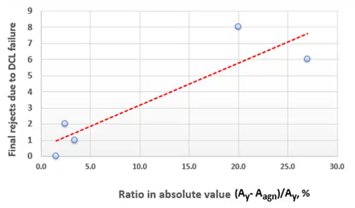
The yield strength of the anode was determined from the stress-strain curve, see Fig. 6., before (Ay) and after artificial aging (Aagn), at room temperature, and their difference (Ay-Aagn) is determined.
The value of the difference between them (reflects) indicates, how much the anode structure has changed during annealing, which can be used as an indicator of the process rate of aging under the same condition aging conditions. An increase in their difference under the same aging conditions indicates an increase in the aging rate and vice versa.
The following Fig.7. shows dependence of tantalum capacitor DCL failures after the life test 2000h, on the difference in the yield strength of the anodes before and after aging. It can be seen that an increase in the percentage ratio of yield strengths leads to an increase in the number of failures of the tantalum capacitors DCL during life-time.
Based on the experimental results we can propose additional anode control method that enables tantalum capacitor life-time reliability and DCL failures prediction. – See Figure 8.
V. Summary
In our test we have evaluated tantalum anode mechanical properties of the same batch that was used in tantalum capacitors that passed life-time tests. Based on the results, relationship between life-time failures and the anode mechanical parameters can be seen. Thus, a reference standard for comparison with similar anodes of this capacitor design can be established to predict its LT failures and yield issues.
A similar approach can be used to control the sintered pellet and any formation parameters – as proposed in Fig.8.
In addition, the proposed method can be used to characterize similar tantalum capacitor designs, such as:
- new batches
- same grade powder of new vendors
- repairing or replacing equipment or human factors
VI. Appendix
Strain-Stress curve parameters description on porous materials
Ау – the yield stress of porous materials, the following equation was obtained which is related to the ratio of the neck size (X) to the size of the primary powder particle (D),
Ay = b*A0*(X/D)2
where
- b is an empirical constant
- Ay is the yield point of the sintered porous material
- A0 is the yield point of the deformed material. (Limited so that X/D does not exceed 0.5).
Е -To describe the behavior of Young’s modulus of a porous material, the following equation was proposed:
E = E0 (1-p/pc)
where
- E is the elastic modulus of a porous material with a porosity of the corresponding density p
- E0 is the modulus of solid material at a density pc ~ 1.
P– exponential hardening coefficient, which correlates with the defectiveness of the material.
Note: The size D determines BET