


Components operating in high vibration and wide operating temperature environments such, as automotive electronics, have to absorb both board flexure stress and stress from the expansion and contraction of solder joints due to thermal shock. Thereby manufactures have developed conductive soft resin-polymer as the thermo-mechanical shock absorber improving connection reliability compare to conventional electrodes. TDK has present its explanation in article below.
Automakers are incorporating more multifunctional capabilities into automobiles as they seek to make autonomous driving a reality. Electronic control units (ECUs) for advanced driver assistance systems are consuming more power, and the latest trend is toward ECU integration—installing an ECU close to the engine room or other working part. For these reasons, the number of electronic devices and components built into cars these days is on the rise, and the reliability of the electronic components used in the electronics is having a growing impact on the reliability of the vehicle overall.
High reliability required for automotive electronic components
As automotive electrical devices become more compact while providing greater functionality, the number of onboard electronic components has been rising at the same time as the functioning environment has become more demanding. Electronic components have the following three desirable qualities:
- Compact
- High performance
- High reliability
High reliability is especially important. Electronic components that have the durability required for mechanical strength and are able to withstand rapid changes in temperature will be in high demand more than ever.
To meet these needs, TDK supplies products with improved connection reliability thanks to resin electrodes (soft termination) used in the capacitors, inductors, and chip beads employed in the products.
This Tech Note discusses examples of and the effects of resin electrodes in dealing with the issues of flex cracks and solder cracks.
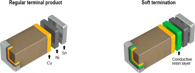
Difference between a regular terminal product and soft termination
Products with resin electrodes absorb both board flexure stress and stress from the expansion and contraction of solder joints due to thermal shock, thereby improving connection reliability over products with conventional electrodes.
Flex cracks that occur in multilayer ceramic chip capacitors (MLCCs)
- In the terminal electrode of a regular MLCC, the Cu under layer is plated with Ni and Sn. Soft termination is a type of MLCC in which a conductive resin layer is provided between the Cu and Ni plating layer. (Fig. 1)
- The resin layer absorbs stress accompanying expansion or shrinkage of the solder joints due to thermal shock or flex stress on the board and prevents cracking of the capacitor element.
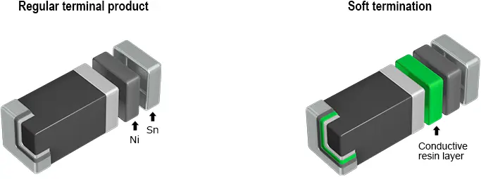
Flex cracks that occur in inductors (coils) and chip beads
- In the terminal electrode of a regular beads, the Ag under layer is plated with Ni and Sn. Soft termination is a type of beads in which a conductive resin layer is provided between the Ag and Ni plating layer. (Fig. 2)
Flex crack countermeasures by using soft termination
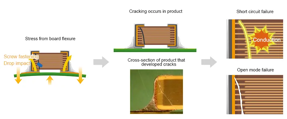
Major causes and process of flex cracks
Flex cracking is due to excessive circuit board flexure. As for the causes of board flexure, there are various causes including solder stress due to an inappropriate amount of solder, stress applied at the time of depaneling or screw fastening, or board flexure at the time of final assembly. When a crack occurs on the element, it may lead to a failure—either a short circuit (mode) or open mode failure—requiring measures to be taken.
Flex cracks that occur in multilayer ceramic chip capacitors (MLCCs)
Whereas excessive stress has caused cracking on the ceramic element of a conventional product, no cracking develops on the element with soft termination, even with peeling of the nickel plating layer and conductive resin layer. This shows that the conductive resin layer has an excellent effect in preventing element cracks. For more information, see the Summary of Flex Crack Countermeasures in MLCCs solution guide.
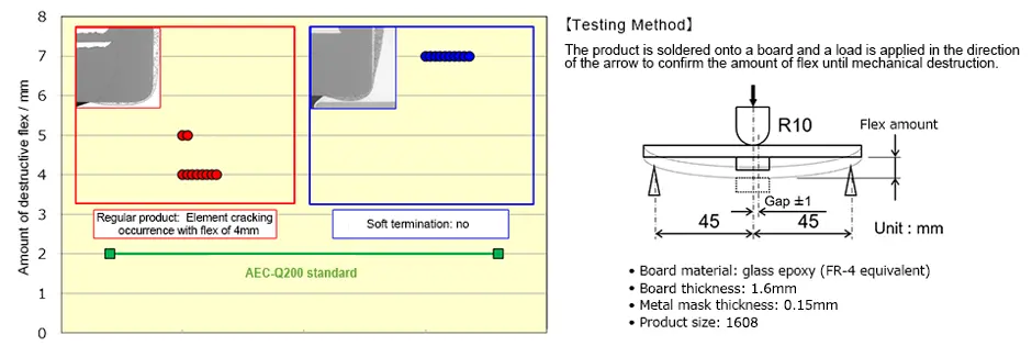
Flex cracks that occur in inductors (coils) and chip beads
TDK’s multilayer inductors and chip bead resin electrode products have nearly twice the board flex resistance (critical bending) of products with conventional electrodes, according to testing. In the conventional product, cracks developed on the ceramic element with a flex of about 4 mm. The product with soft termination can safely withstand cracking at 7 mm of flex.
Solder crack countermeasures by using soft termination
Major causes and process of solder cracks
Solder cracks on electronic components developed from severe usage conditions after going on the market and during manufacturing processes such as soldering. The primary cause of cracking is the difference between the thermal expansion coefficient of the product’s electrodes and its board in an environment of repeated temperature changes, resulting in thermal stress on the soldered areas.
In automobiles in particular, caution is required because of the high likelihood of rapid temperature changes (thermal shock) occurring in close proximity to the product. Because of environmental considerations, lead-free solder has come to be used even for automotive electronic components, and the risk of solder cracking is increasing when compared to the use of conventional eutectic solder in terms of temperature control and solder composition.
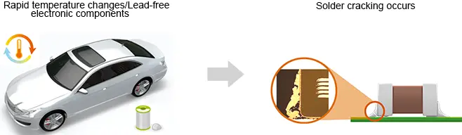
Fig. 5: Major causes of solder cracks
Bond strength decrease rate
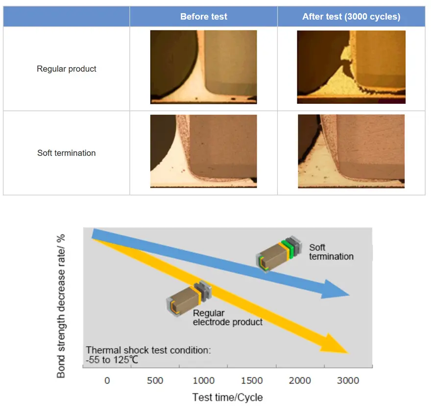
In general, anchoring strength declines after a thermal shock, but TDK’s resin electrodes feature excellent thermal shock resistance, a fact borne out by post-thermal shock test data.
Flex cracks that occur in multilayer ceramic chip capacitors (MLCCs)
- The 3,000-cycle thermal shock test data (-55 °C to 125 °C) show that the anchoring strength of the conventional product declined approximately 90%, as compared to approximately 50% for the resin electrode.
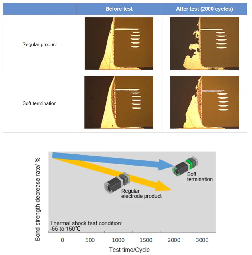
Flex cracks that occur in inductors (coils) and chip beads
- •The 2,000-cycle thermal shock test data (-55 °C to 150 °C) show that the anchoring strength of the conventional product declined approximately 50%, as compared to approximately 20% for the resin electrode.
Summary
When the element of an electronic component develops cracking, a short circuit failure or open circuit failure will occur.
Similarly, solder cracking will occur when there is stress between the board and the joint, causing the component to possibly fall off or an open circuit failure or other failure to occur.
Caution is required when components are used in locations with extreme temperature changes (differences) such as in an automobile’s engine room or on a device with a heat source.
TDK’s soft termination products are highly resistant to board bending and flexure and to thermal shock, and can suppress external stresses. TDK supplies electronic components with soft termination to improve connection reliability.
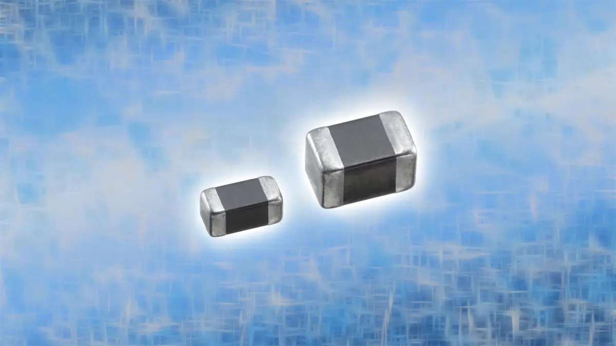
featured image: TDK inductors and chip beads with soft termination; source: TDK


