Passive Components Blog
No Result
View All Result
  • Home
  • NewsFilter
    • All
    • Aerospace & Defence
    • Antenna
    • Applications
    • Automotive
    • Capacitors
    • Circuit Protection Devices
    • electro-mechanical news
    • Filters
    • Fuses
    • Inductors
    • Industrial
    • Integrated Passives
    • inter-connect news
    • Market & Supply Chain
    • Market Insights
    • Medical
    • Modelling and Simulation
    • New Materials & Supply
    • New Technologies
    • Non-linear Passives
    • Oscillators
    • Passive Sensors News
    • Resistors
    • RF & Microwave
    • Telecommunication
    • Weekly Digest

    Binder Hybrid Connector Simplifies One Cable Automation

    Tapped Inductor Buck Converter Fundamentals

    TAIYO YUDEN Releases Mini Metal Power Inductors

    Molecular Memristor Shows Record 145 kH Emergent Inductance

    Planar vs Conventional Transformer: When it Make Sense

    Researchers Propose Next‑Gen Compact Memory Using Ultra-thin Ferroelectric Capacitors

    Nichicon ADN Automotive Hybrid Aluminum Capacitors Now Available in EMEA

    Wk 19 Electronics Supply Chain Digest

    Electrocaloric Multilayer Capacitors: Towards Quiet, Solid‑State Cooling Around Room Temperature

    Trending Tags

    • Ripple Current
    • RF
    • Leakage Current
    • Tantalum vs Ceramic
    • Snubber
    • Low ESR
    • Feedthrough
    • Derating
    • Dielectric Constant
    • New Products
    • Market Reports
  • VideoFilter
    • All
    • Antenna videos
    • Capacitor videos
    • Circuit Protection Video
    • Filter videos
    • Fuse videos
    • Inductor videos
    • Inter-Connect Video
    • Non-linear passives videos
    • Oscillator videos
    • Passive sensors videos
    • Resistor videos

    Tapped Inductor Buck Converter Fundamentals

    Planar vs Conventional Transformer: When it Make Sense

    Modeling Fringing Field Losses in Inductors & Transformers

    Why Power Inductors Use a Ferrite Core With an Air Gap

    Transformer-Based Power-Line Harvester Magnetic Design

    Thermal Modeling of Magnetics

    Standard vs Planar LLC transformers Comparison for Battery Chargers

    How Modern Tools Model Magnetic Components for Power Electronics

    Advanced Loss Modeling for Planar Magnetics in the Frenetic Planar Tool

    Trending Tags

    • Capacitors explained
    • Inductors explained
    • Resistors explained
    • Filters explained
    • Application Video Guidelines
    • EMC
    • New Products
    • Ripple Current
    • Simulation
    • Tantalum vs Ceramic
  • Knowledge Blog
  • DossiersNew
  • Suppliers
    • Who is Who
  • PCNS
    • PCNS 2025
    • PCNS 2023
    • PCNS 2021
    • PCNS 2019
    • PCNS 2017
  • Events
No Result
View All Result
Passive Components Blog
No Result
View All Result

TDK: Guide for replacing of film capacitors with MLCC

28.7.2017
Reading Time: 5 mins read
A A

source: TDK news

TDK published a technical note guide for replacing of film capacitors with C0G MLCC.

RelatedPosts

Binder Hybrid Connector Simplifies One Cable Automation

Tapped Inductor Buck Converter Fundamentals

TAIYO YUDEN Releases Mini Metal Power Inductors

Vol.1 Features of High voltage MLCCs with C0G Characteristics and Replacement Solutions Overview

A wide variety of capacitors, each with their own special characteristics, are used in electronic devices. Generally speaking, the capacitance and withstand voltage (rated voltage) of capacitors are in a trade-off relationship which is difficult to balance. In MLCC of the same size, when increasing the withstand voltage, the capacitance tends to decrease.
Film capacitors possess a good balance of high withstand voltage and capacitance. Since they also possess outstanding frequency characteristics and temperature characteristics, they are widely used in automotive electronics, industrial equipment, home appliances, etc.

However, in recent years, there have been remarkable increases in withstand voltage and capacitance in MLCCs (multilayer ceramic chip capacitors) for temperature compensation (class 1). In particular, even in fields where film capacitors have traditionally been used, resonance circuits for example, replacement with MLCC is now possible. TDK has developed high voltage MLCCs with C0G characteristics. Through C0G characteristics, these MLCCs achieve withstand voltage of 1000V at the broadest capacitance range (1nF to 33nF) in the industry.

In this guide, we explain the numerous benefits of replacement while comparing the features of high voltage C0G MLCCs with those of film capacitors.

Characteristics of main capacitors
MLCCs are divided into two major categories according to the type of ceramic materials used for their dielectric, namely class 1 (temperature compensating) and class 2 (high dielectric constant).
Class 2 MLCCs have a large capacitance. However, they also have a disadvantage in terms of a large capacitance change caused by temperature. On the other hand, while class 1 MLCCs do not offer as high a capacitance as class 2, they display a smaller capacitance change caused by temperature. They also possess outstanding frequency characteristics and are used in circuits which require high precision.

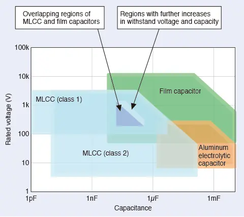
Figure 1 shows the corresponding regions for rated voltage-capacitance in main capacitors: aluminum electrolytic capacitors, film capacitors, and MLCCs (class 1 and class 2).

Figure 1: Corresponding regions of rated voltage-capacitance for different capacitors

Figure 1: Corresponding regions of rated voltage-capacitance for different capacitors
In terms of capacitance, class 2 MLCCs achieve a capacitance of more than 100μF, as offered by aluminum electrolytic capacitors. Furthermore, even in the past, class 1 MLCC voltage-capacitance overlapped a portion of film capacitor regions. However, the withstand voltage and capacitance have increased in recent years, and the overlapping regions are increasing rapidly.
Table 1 summarizes a comparison of the characteristics of aluminum electrolytic capacitors, film capacitors, and MLCCs.

Table 1: Comparison of characteristics in main capacitors

Aluminum electrolytic
capacitor
Film
capacitor
MLCC
(class 1)
MLCC
(class 2)
Large capacitance ◎ ○ △ ○
Withstand voltage ○ ◎ ○ ○
Temperature characteristics △ ◎ ◎ △
Frequency characteristics △ ◎ ◎ ◎
DC bias characteristics ◎ ◎ ◎ △
Ripple resistance △ ◎ ◎ ◎
Moisture resistance ○ ○ ◎ ◎
Lifespan/reliability △ ◎ ◎ ◎
Compact size △ △ ◎ ◎

◎: Outstanding ○: Good △: Relatively poor

The advantage of aluminum electrolytic capacitors is their large capacitance. In terms of other characteristics, film capacitors and MLCCs are superior. Unlike class 1 MLCCs, it is difficult to achieve compact size for film capacitors. The table also shows how it is difficult to increase the capacitance and withstand voltage of class 1 MLCCs.

The capacitance value of class 2 MLCCs changes greatly with changes in temperature. In comparison, class 1 MLCCs exhibit a nearly linear change. The straight line slope in relation to temperature is called the “temperature coefficient.” It is expressed in units of [ppm/°C].
In JIS and EIA standards, the temperature coefficient value and the related tolerance are categorized into classes. The strictest EIA standards for C0G MLCCs (class 1) require a temperature coefficient of 0 ppm/°C and a tolerance of ±30 ppm/°C at a temperature range of -55 to +125°C. Figure 2 shows temperature characteristics (changes in capacitance due to temperature change) for film capacitors and MLCCs.

Figure 2: Comparison of temperature characteristics (changes in capacitance due to temperature change) in C0G MLCCs and various capacitors

Figure 2: Comparison of temperature characteristics (changes in capacitance due to temperature change) in C0G MLCCs and various capacitors

As clearly shown by the graph, C0G MLCCs have extremely stable temperature characteristics when compared with X7R MLCCs (class 2), U2J MLCCs (class 1), and various film capacitors.

Reason why C0G MLCCs are used in resonance circuits
The resonance frequency (f) of LC resonance circuits with a combination of capacitors and coils (inductors) is expressed by the formula f=1/2π√LC, where C is the capacitance of the capacitor, and L is the inductance of the coil. As shown by this formula, changes in the capacitance of the resonance capacitor (capacitor in a resonance circuit) cause changes in the resonance frequency. When the resonance frequency does not remain stable and fluctuates, warping occurs in the waveform transmitted and the energy transmission efficiency decreases.
For this reason, film capacitors which are relatively stable in relation to temperature change have normally been used in resonance circuits for automotive electronics and other devices with large currents at high voltages.
Also shown by the formula above, capacitors with even larger capacitance are required as the resonance frequency decreases. The resonance frequency for resonance circuits of automotive electronics is set to a range of several tens kHz to several hundreds kHz, and film capacitors with both a high withstand voltage and capacitance were most suitable for this usage.
However, as stated earlier, the withstand voltage and capacitance of class 1 MLCC is increasing rapidly in recent years, and more and more manufacturers are replacing film capacitors with C0G MLCCs as a result. MLCCs are smaller than film capacitors, and so have the advantages of increasing transmission efficiency through high-accuracy resonance and compact size.
Table 2 shows a comparison of temperature range, moisture resistance, external shape, and size of film capacitors (PP: Polypropylene) and C0G MLCCs.

Table 2: Comparison of main specifications for film capacitors and C0G MLCCs

Film capacitor A
(PP)
Film capacitor B
(PP)
C0G
MLCC
Temperature range -40 to
+105°C
-40 to
+105°C
-55 to
+125°C
Moisture resistance 40°C/
95%RH
60°C/
95%RH
85°C/
85%RH
External shape, size Lead terminal,
large size
Lead terminal,
Medium size
SMD, small size
(lead terminal also exists)


continue reading at the TDK site after registration here

Related

Recent Posts

Binder Hybrid Connector Simplifies One Cable Automation

13.5.2026
3

Planar vs Conventional Transformer: When it Make Sense

11.5.2026
35

Researchers Propose Next‑Gen Compact Memory Using Ultra-thin Ferroelectric Capacitors

11.5.2026
28

Nichicon ADN Automotive Hybrid Aluminum Capacitors Now Available in EMEA

11.5.2026
22

Electrocaloric Multilayer Capacitors: Towards Quiet, Solid‑State Cooling Around Room Temperature

7.5.2026
184

Stackpole Expanded its AlN Thick Film Chip Resistors

6.5.2026
22

KYOCERA 10 µF 0201 MLCC Brings High‑Capacitance into Mobile Designs

6.5.2026
52

Würth Elektronik Introduces Compact Flat-wire SMT Power Inductors for Automotive

5.5.2026
49

KYOCERA AVX Extends MLV Varistors for 48V Automotive Protection

5.5.2026
26

Upcoming Events

May 13
17:00 - 17:30 CEST

Winding Loss Modeling for Toroidal Magnetics – Including Gapped Cores

May 19
16:00 - 17:00 CEST

Designing Qi2 Wireless Power Systems: Practical Development and EMC Optimization

Jun 2
16:00 - 17:00 CEST

Calculation, Simulation and Measurement of 800V EMC Filters

View Calendar

Popular Posts

  • Buck Converter Design and Calculation

    0 shares
    Share 0 Tweet 0
  • Boost Converter Design and Calculation

    0 shares
    Share 0 Tweet 0
  • Flyback Converter Design and Calculation

    0 shares
    Share 0 Tweet 0
  • LLC Resonant Converter Design and Calculation

    0 shares
    Share 0 Tweet 0
  • MLCC and Ceramic Capacitors

    0 shares
    Share 0 Tweet 0
  • Dual Active Bridge (DAB) Topology

    0 shares
    Share 0 Tweet 0
  • What Electronics Engineer Needs to Know About Passive Low Pass Filters

    0 shares
    Share 0 Tweet 0
  • Capacitor Charging and Discharging

    0 shares
    Share 0 Tweet 0
  • Ripple Current and its Effects on the Performance of Capacitors

    3 shares
    Share 3 Tweet 0
  • MLCC Case Sizes Standards Explained

    0 shares
    Share 0 Tweet 0

Newsletter Subscription


Passive Components Blog

© EPCI - Leading Passive Components Educational and Information Site

  • Home
  • Privacy Policy
  • EPCI Membership & Advertisement
  • About

No Result
View All Result
  • Home
  • Knowledge Blog
  • PCNS

© EPCI - Leading Passive Components Educational and Information Site

This website uses cookies. By continuing to use this website you are giving consent to cookies being used. Visit our Privacy and Cookie Policy.
Go to mobile version