Passive Components Blog
No Result
View All Result
  • Home
  • News
    • All
    • Aerospace & Defence
    • Antenna
    • Applications
    • Automotive
    • Capacitors
    • Circuit Protection Devices
    • electro-mechanical news
    • Filters
    • Fuses
    • Inductors
    • Industrial
    • Integrated Passives
    • inter-connect news
    • Market & Supply Chain
    • Market Insights
    • Medical
    • Modelling and Simulation
    • New Materials & Supply
    • New Technologies
    • Non-linear Passives
    • Optoelectronics and Isolation
    • Oscillators
    • Passive Sensors News
    • Resistors
    • RF & Microwave
    • Telecommunication
    • Weekly Digest
    Silicon capacitors and integrated passives dossier cover

    Silicon Capacitors and Integrated Passives Dossier Report 10/26

    Samtec automotive interconnect technologies for software-defined vehicle electronics

    Samtec Links Automotive Connector Demands to Software-Defined Cars

    Panasonic Industry PGS graphite heat-spreading technology and passive components for spacecraft thermal management

    Panasonic Targets Space Thermal Design at SPCD 2026

    tungsten-bronze-ceramic-capacitor-stack

    Tungsten bronze capacitors combine high κ and thermal stability

    Bourns MF-ASMF Series surface-mount PPTC resettable fuses in the manufacturer product photograph

    Bourns Announces 0402 PPTC Fuses Target Low-Current Protection

    Conceptual illustration of Littelfuse AQ4315-01ETG and SP4315-01WTG TVS diode applications on high-speed PCB data lines

    Littelfuse Adds Low-Capacitance TVS Diodes for Fast Data Links

    Datasheet-style illustration of a TDK MLJ1608-G multilayer chip inductor with end terminals

    TDK Expands1608 Inductors for Automotive PoC Filters

    Murata electronica 2026 technology preview featuring MGJ2T2 power converters and SCI36LT inertial sensors.

    Murata Previews SiC Power and AI Sensors at electronica 2026

    Ruggedized passive component customization overview covering capacitors, resistors and inductors.

    Ruggedized Passive Components: Reliability Beyond the Datasheet

    Trending Tags

    • Ripple Current
    • RF
    • Leakage Current
    • Tantalum vs Ceramic
    • Snubber
    • Low ESR
    • Feedthrough
    • Derating
    • Dielectric Constant
    • New Products
    • Market Reports
  • Knowledge Blog
  • Dossiers
    • Aerospace and Defense Passive Components Dossier
    • AI Hardware Dossier
    • Automotive Dossier
    • Industrial Robotics Dossier
    • Power Converter Dossier
    • Capacitor Dossier
    • Circuit Protection Dossier
    • Inductor Dossier
    • Resistor Dossier
    • Silicon Capacitors and Integrated Passives Dossier
  • Suppliers
    • Who is Who
  • PCNS
    • PCNS 2025
    • PCNS 2023
    • PCNS 2021
    • PCNS 2019
    • PCNS 2017
  • Events
  • Home
  • News
    • All
    • Aerospace & Defence
    • Antenna
    • Applications
    • Automotive
    • Capacitors
    • Circuit Protection Devices
    • electro-mechanical news
    • Filters
    • Fuses
    • Inductors
    • Industrial
    • Integrated Passives
    • inter-connect news
    • Market & Supply Chain
    • Market Insights
    • Medical
    • Modelling and Simulation
    • New Materials & Supply
    • New Technologies
    • Non-linear Passives
    • Optoelectronics and Isolation
    • Oscillators
    • Passive Sensors News
    • Resistors
    • RF & Microwave
    • Telecommunication
    • Weekly Digest
    Silicon capacitors and integrated passives dossier cover

    Silicon Capacitors and Integrated Passives Dossier Report 10/26

    Samtec automotive interconnect technologies for software-defined vehicle electronics

    Samtec Links Automotive Connector Demands to Software-Defined Cars

    Panasonic Industry PGS graphite heat-spreading technology and passive components for spacecraft thermal management

    Panasonic Targets Space Thermal Design at SPCD 2026

    tungsten-bronze-ceramic-capacitor-stack

    Tungsten bronze capacitors combine high κ and thermal stability

    Bourns MF-ASMF Series surface-mount PPTC resettable fuses in the manufacturer product photograph

    Bourns Announces 0402 PPTC Fuses Target Low-Current Protection

    Conceptual illustration of Littelfuse AQ4315-01ETG and SP4315-01WTG TVS diode applications on high-speed PCB data lines

    Littelfuse Adds Low-Capacitance TVS Diodes for Fast Data Links

    Datasheet-style illustration of a TDK MLJ1608-G multilayer chip inductor with end terminals

    TDK Expands1608 Inductors for Automotive PoC Filters

    Murata electronica 2026 technology preview featuring MGJ2T2 power converters and SCI36LT inertial sensors.

    Murata Previews SiC Power and AI Sensors at electronica 2026

    Ruggedized passive component customization overview covering capacitors, resistors and inductors.

    Ruggedized Passive Components: Reliability Beyond the Datasheet

    Trending Tags

    • Ripple Current
    • RF
    • Leakage Current
    • Tantalum vs Ceramic
    • Snubber
    • Low ESR
    • Feedthrough
    • Derating
    • Dielectric Constant
    • New Products
    • Market Reports
  • Knowledge Blog
  • Dossiers
    • Aerospace and Defense Passive Components Dossier
    • AI Hardware Dossier
    • Automotive Dossier
    • Industrial Robotics Dossier
    • Power Converter Dossier
    • Capacitor Dossier
    • Circuit Protection Dossier
    • Inductor Dossier
    • Resistor Dossier
    • Silicon Capacitors and Integrated Passives Dossier
  • Suppliers
    • Who is Who
  • PCNS
    • PCNS 2025
    • PCNS 2023
    • PCNS 2021
    • PCNS 2019
    • PCNS 2017
  • Events
No Result
View All Result
Passive Components Blog
No Result
View All Result

Understanding Capacitor Leakage Current

1.6.2022
Reading Time: 7 mins read
A A

Analyzing the leakage current from capacitors in the circuit of smart devices and selecting alternative components to reduce leakage could allow smart devices to last longer.

The spread of the IoT has driven up demand for smart devices such as sensors or actuators that are self-powered or able to run for long periods up to several years from an energy source as small as a coin cell. The art of ultra-low-power design has quickly become extremely sophisticated, all the way from the energy-harvesting or battery-management system to the antenna, turning off any subsystems when not needed and getting the maximum from every joule.

RelatedPosts

Failure Analysis of Capacitors and Inductors

Schaffner introduces low leakage current 3phase EMI filter

Sumida Introduces High Current and Low DC Resistance Power Inductor

Despite energy-conscious circuit and software design, capacitor leakage could thwart your struggle to make the available milliamp-hours last for long enough. Multiple capacitors are typically needed to stabilize the power from an energy-harvesting system, or DC/DC converter and when charged behave like leaky buckets that continually allow a small amount of charge to dissipate, wasting precious energy.

Although only a few microamps, the leakage current can be comparable to the amount you might go to great lengths to divert, say, from the microcontroller through intricate use of power-saving modes. It makes sense to analyze the leakage current from capacitors in the circuit and consider selecting alternative components to reduce it.

Opportunities for Savings
Figure 1 shows the reservoir capacitor network recommended for a PIR-sensor reference design published by TI, comprising five capacitors. Ten years’ maintenance-free operation is a common target for this type of product, but poorly selected capacitors could draw more current than the coin cell can deliver for 10 years.
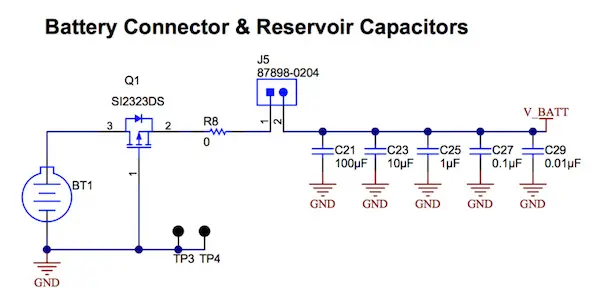
Figure 1. Battery energy can be lost through power-supply filtering and stabilization capacitors.

Similarly, in an energy-harvesting system, a large capacitance is needed to drive the application and is calculated according to the average power consumption. A small portion of the energy collected by the harvesting mechanism, such as a solar cell or Peltier module, is stored in the capacitors and lost as these discharge over time.

Technology Choices

Choosing the right technology, voltage rating, and capacitance value can make a huge difference in the amount of energy lost to leakage. Let’s take a look at ceramic capacitors (MLCCs), which are widely used to filter power-supply noise and provide hold-up energy to cover interruptions in power delivery or ensure shut-down can complete properly. Because the leakage current is small, the effect is quantified in terms of the device’s insulation resistance: a higher insulation resistance implies lower leakage.

The MLCC comprises multiple parallel plates separated by the ceramic dielectric. Generally, the highest possible capacitance value is desirable, in the smallest possible case size. Capacitor manufacturers have developed thin dielectric layers, fine particles, and precision lamination technologies to boost capacitance within the size constraints of standard SMD case sizes. On the other hand, thicker dielectric layers are needed to achieve a higher voltage rating: increasing the voltage rating increases the insulation resistance and hence reduces leakage, although capacitance is also lower if the case size remains the same.

We can see how the dielectric thickness, applied voltage, and electron mobility influence leakage current. The electric field within the capacitor exerts a force on charged particles:

F = E*q = U/d * q

This force drives the flow of electrons within the device, which constitutes the leakage current. For a given applied voltage, it is clear that the force F and therefore the leakage current will increase as the dielectric thickness, d, reduces.

Another way to relate capacitance to case size is through the equation:
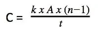
We can see that if we want to keep the same capacitance while decreasing the area (e.g. 0812 to 0402), then we can either reduce the dielectric thickness or increase the number of layers. The most likely approach is to use a combination of both. Overall, we can see that downsizing the capacitor inherently increases leakage.

We must also be aware of the change in leakage over temperature. As the mobility of charged particles increases with temperature, so, too, does the leakage. In practice, MLCC leakage increases by a factor of more than seven between room temperature and 45°C.

Calculating Leakage Current
Calculating the leakage current allows an assessment of its effect on battery runtime. Note that immediately after voltage is applied, the current initially flowing in the capacitor comprises the charging current and dielectric absorption currents, as well as the leakage current. As the charging current and absorption currents decay, the current flowing converges to the leakage current.

The datasheet for a ceramic capacitor states the guaranteed minimum insulation resistance, or insulation resistance limit, in Ohm-Farad (Ω-F), in terms of the case size and capacitance value. To calculate the insulation resistance for a given capacitor, simply look up the specified Ohm-Farad figure for the device and divide by the capacitance value. The leakage current at the working voltage can then be calculated by applying Ohm’s law:

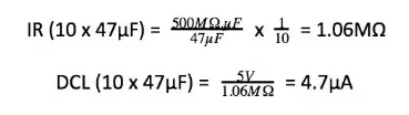
Consider this example, if using 10x 47µF commercial X7R MLCCs for power-rail filtering, at a working voltage of 5V. The datasheet guarantees an insulation resistance specification of 500MΩ.µF for this device:
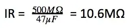
The DC leakage for the array of 10 capacitors can then be calculated:
Tantalum Capacitors
Tantalum capacitors are characterized by high volumetric efficiency, low noise, and stability over time, making them an excellent choice for power-constrained IoT devices that are required to operate maintenance-free over an extended lifetime.

For these types of capacitors, assessing the DC leakage current is somewhat easier than for ceramic capacitors. The datasheet expresses the DC leakage current directly as a fraction of the capacitance value and voltage. For the KEMET T491 standard MnO2 capacitor series, this expression is:

DCL = 0.01 x C x V

Hence for 470µF capacitance with an applied voltage of 5V, comparable to the previous example, the DC leakage is:

DCL = 0.01 x C x V = 0.01 x 470 x 5 = 23.5µA

For the KEMET T489 series, which is engineered specifically for low leakage, the expression is:

DCL = 0.0075 x C x V = 0.0075 x 470 x 5 = 17.6µA

Hence, replacing T491 capacitors with 470µF of T489 devices can achieve a valuable reduction in leakage current.

In tantalum capacitors, the leakage current is heavily dependent on the ratio of rated applied voltage to rated voltage, due to the link between voltage rating and dielectric thickness. The graph of Figure 2 shows how leakage current is significantly reduced when the applied voltage is much lower than the rated voltage.
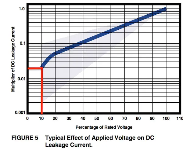
Figure 2. Typical variation of DC leakage with applied-voltage/rated-voltage ratio. 

Specifying a capacitor with a rated voltage 10 times higher than the applied voltage can reduce the DC leakage by a factor of 50. Designers can take advantage of this in circuits where very low leakage current is required, at the expense of an increase in device size.

Note that leakage is also dependent on temperature so this, too, should be taken into account when calculating the effect on the system energy budget.

Capacitor DC Leakage is an Important Design Consideration

Capacitor DC leakage phenomenon is important to consider when designing ultra-low-power systems or devices that must operate for a long period without charging or replacing the battery. Examples include PIR sensors or energy-harvesting systems that require large capacitance to maintain a stable supply of energy to the system.

It is worth calculating the effect of leakage current on the energy budget for the system as a whole to determine any necessary mitigation. Ceramic capacitors with high capacitance values tend to have higher DC leakage. On the other hand, devices of higher voltage rating benefit from lower leakage but also have less capacitance in relation to package size. Leakage can be reduced by specifying capacitors from a dedicated low-leakage family, such as the T498 tantalum series.


Related

Source: KEMET

Recent Posts

Silicon capacitors and integrated passives dossier cover

Silicon Capacitors and Integrated Passives Dossier Report 10/26

8.10.2026
1
Panasonic Industry PGS graphite heat-spreading technology and passive components for spacecraft thermal management

Panasonic Targets Space Thermal Design at SPCD 2026

8.10.2026
8
tungsten-bronze-ceramic-capacitor-stack

Tungsten bronze capacitors combine high κ and thermal stability

7.10.2026
14
Ruggedized passive component customization overview covering capacitors, resistors and inductors.

Ruggedized Passive Components: Reliability Beyond the Datasheet

6.10.2026
21
TDK B3272 series boxed DC-link film capacitors with radial leads for automotive and industrial power-electronics applications

TDK Expanded DC-Link Film Capacitors to Reach +135 °C

2.10.2026
24
Film DC-link capacitor and supercapacitor energy buffer in a high-voltage power converter system

Electrification Raises Demands on DC-Link Capacitors

1.10.2026
29
YAGEO Group high-reliability polymer tantalum capacitor portfolio for aerospace and defence power electronics

YAGEO High-Reliability Polymer Tantalum Capacitors for Aerospace

1.10.2026
38
Schematic of the step-wise LPG/LPG@MnOx/LPG-O functionally graded thick cathode for a zinc-ion hybrid capacitor, Hefei Institutes of Physical Science.

Laser-Engineered Zinc-Ion Cathodes Target Thick Electrodes

1.10.2026
15
Two Murata LLD three-terminal MLCCs beside a metal ruler, showing beige ceramic bodies and silver-coloured terminals.

Murata Begins Production of 0201 Three-Terminal Low-ESL MLCCs for IC Decoupling

30.9.2026
44

Upcoming Events

Oct 9
18:00 - 19:00 CEST

Edgewater Research 3Q26 Electronic Components Review Outlook Webinar

Oct 14
17:00 - 18:00 CEST

Live Demo! Discover KYOCERA AVX Antenna Integrator Studio (AIS)

Oct 19
15:00 - 16:00 CEST

ESCC-qualified Pt Temperature Sensors for Space Applications

View Calendar

Popular Posts

  • Buck Converter Design and Calculation

    0 shares
    Share 0 Tweet 0
  • Boost Converter Design and Calculation

    0 shares
    Share 0 Tweet 0
  • LLC Resonant Converter Design and Calculation

    0 shares
    Share 0 Tweet 0
  • Flyback Converter Design and Calculation

    0 shares
    Share 0 Tweet 0
  • Capacitor Charging and Discharging

    0 shares
    Share 0 Tweet 0
  • Resistor Symbols

    0 shares
    Share 0 Tweet 0
  • Audio Capacitors: Choosing Capacitors for Crossover Circuits

    0 shares
    Share 0 Tweet 0
  • Thermistors Basics, NTC and PTC Thermistors

    0 shares
    Share 0 Tweet 0
  • MLCC and Ceramic Capacitors

    0 shares
    Share 0 Tweet 0
  • RF Connector Types: How To Choose the Right One

    0 shares
    Share 0 Tweet 0

Newsletter Subscription


Passive Components Blog

© 2015–2026
All rights reserved

  • Home
  • Privacy Policy
  • EPCI Membership & Advertisement
  • About

No Result
View All Result
  • Home
  • Knowledge Blog
  • Dossiers
  • PCNS

© 2015–2026
All rights reserved